Presentation of the Microsemi Adaptec maxView Storage Manager v4 / v3 web interface
- RAID
- 19 May 2024 at 15:34 UTC
-

- 2/5

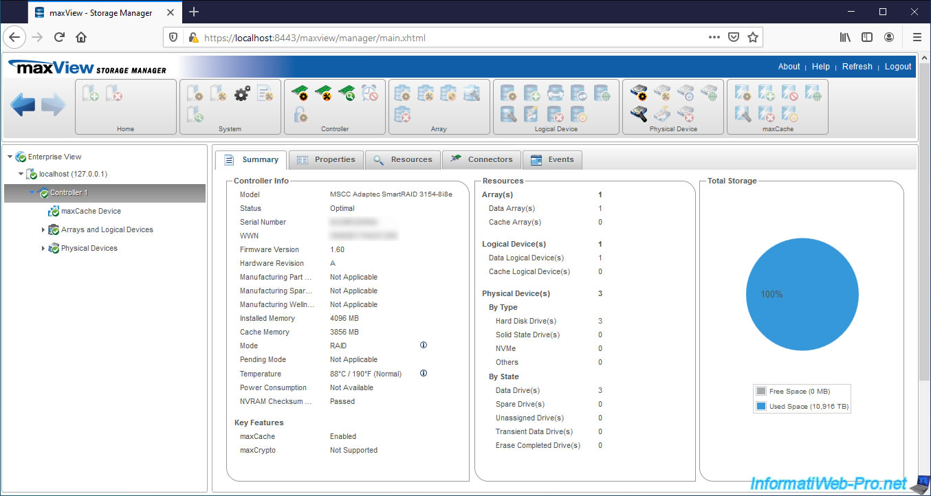
3.4. Information about your Microsemi Adaptec controller
In the "Summary" tab of the desired controller, you will find :
- Model : his model. In our case : MSCC Adaptec SmartRAID 3154-8i8e.
- Status : his status. Optimal = all is well, Warning = a warning or a non-urgent problem has been detected and Error = an important problem has been detected
- Serial Number : its serial number
- WWN : unique identifier (World Wide Name) assigned to your Microsemi Adaptec controller
- Firmware Version : firmware version present on your controller. This firmware is stored in a chip on your Microsemi SmartRAID controller.
- Hardware Revision : revision code of your Microsemi SmartRAID controller
- Manufacturing Part Number : part number defined by the manufacturer (if applicable)
- Manufacturing Spare Part Number : spare part number defined by the manufacturer (if applicable)
- Manufacturing Wellness Log : information defined by the manufacturer (if applicable)
- Installed Memory : amount of DRAM (Dynamic Random Access Memory) present on your Microsemi SmartRAID controller. In our case : 4096 MB (4 GB).
- Cache Memory : size of the cache memory present on your Microsemi SmartRAID controller. In our case : 3856 MB (3.8 GB).
- Mode : overall functional mode of your Microsemi SmartRAID controller. Note that with SmartRAID controllers, you can choose between : RAID, HBA or Mixed (both at the same time on the same controller)
- Pending Mode : if you change the functional mode of your RAID controller, the value of Pending Mode will be set and will appear as "Mode" after restarting your computer / server.
- Temperature : current operating temperature of your Microsemi SmartRAID controller in degrees Celsius and degrees Fahrenheit. In parentheses, maxView Storage Manager also tells you if this temperature is normal or too high.
Warning : the temperature displayed here is that of the processor. However, this temperature is higher than that measured at one inch from the RAID processor and is therefore higher than that one indicated on the page of your SmartRAID controller. - Power Consumption : energy consumption (if applicable)
- NVRAM Checksum : non-volatile RAM (NVRAM) checksum status
For Key Features, you will see if :
- maxCache is enabled or disabled.
Info : maxCache allows you to use one or more SSDs as a cache for storing frequently used data and is available in version 4.0 on the SmartRAID 3100 Series and 3162 Series controllers, and version 3.0 on the Series 8Q RAID controllers.
Warning : the "Not supported" value can also appear temporarily when you have a battery (eg ASCM-35F) because it's not yet fully charged.
In this case, in the "Properties" tab, you will see that the value of "Backup Power Status" will be "Not Fully Charged". - maxCrypto is supported or not.
Info : maxCrypto allows you to encrypt data on your hard drives connected to your compatible Microsemi Adaptec controller, as well as in the cache. This allows data to be encrypted and decrypted on the fly when you need it.
The advantage of controller encryption is that it's the hardware that will handle the encryption and decryption of data on the fly. The resources (CPU and RAM) of your computer will therefore not be affected.
For resources, you will find :
- Arrays : the number of RAID volumes configured as storage (Data Arrays) or as cache / maxCache (Cache Arrays)
- Logical Devices : the number of logical drives created through your Microsemi Adaptec SmartRAID controller and configured as storage (Data Logical Devices) or as cache / maxCache (Cache Logical Devices)
- Physical Devices : the number of physical hard drives (Hard Disk Drives), SSDs (Solid State Drives), NVMe format SSDs (NVMe) and other peripherals (Others) connected to your Microsemi Adaptec controller
- By State : the number of hard drives or SSDs in good state used for storage (Data Drives), as spare HDD or SSD (Spare Drives), unassigned (Unassigned Drives), transient when a physical drive is removed from a physical disk array (Array) and will become unassigned (Transient Data Drives) or which has been erased and is now offline (Erase Completed Drives).
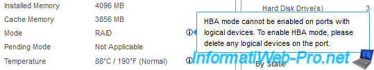
Note that the default operating mode for Microsemi Adaptec SmartRAID controllers is RAID, but you can also use HBA mode on ports where you have not yet created logical drives.
If you only have one port, you will need to delete your RAID volumes first before you can change the functional mode to HBA.
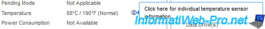
As previously indicated, the temperature shown in the "Controller Info" column is that of the RAID processor of your Microsemi Adaptec SmartRAID controller.
To obtain all the temperatures read by your Microsemi Adaptec SmartRAID controller, click on the small "i" to the right of it.
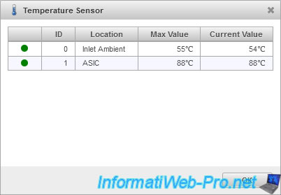
In our case, our Microsemi Adaptec SmartRAID 3154-8i8e controller has 2 temperature probes :
- Inlet Ambient : Max Value 55°C / Current Value 54°C
- ASIC : Max Value 88°C / Current Value 88°C
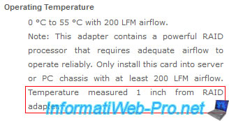
If you look at page 78 of the "Installation and User Guide - Adaptec® SmartRAID 3100 Series and SmartHBA 2100 Series Host Bus Adapters" PDF, you will see that the ambient temperature is measured 1 inch from the processor.
And on page 12, you will see that our Microsemi Adaptec SmartRAID 3154-8i8e controller has 2 temperature sensors : 1 for ambient temperature (Inlet Ambient) and another for processor temperature (ASIC).
If you look on the page of your Microsemi Adaptec SmartRAID controller, you will see that Microsemi is telling you the temperature which is measured 1 inch from the RAID processor.
It's therefore the "Inlet Ambient" value that you must look at and not the other (ASIC = processor).
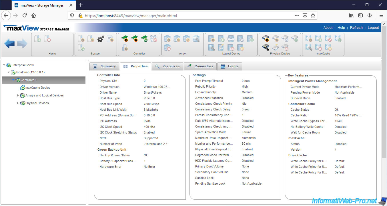
In the "Properties" tab, you will find a lot of information about your RAID controller (connection and driver), the status of the ASCM-35F battery, its settings, as well as information about key features including, the bezel of your Microsemi SmartRAID controller.
For information about the Controller (Controller Info), you will find :
- Physical Slot : the number of the PCI slot to which it's connected
- Driver Version : the version of the driver used to access your Microsemi Adaptec SmartRAID controller. In our case, it is the driver for Windows in version 106.278.0.1043 Build QA
- Driver Name : the name of the driver used. In our case : SmartPqi.sys.
- Host Bus Type : the supported PCI Express (PCIe) version. In this case : PCIe 3.0.
- Host Bus Speed : the PCIe bus speed. Ex : 7880 MBps.
- Host Bus Link Width : Same. Ex : 8 bits/links.
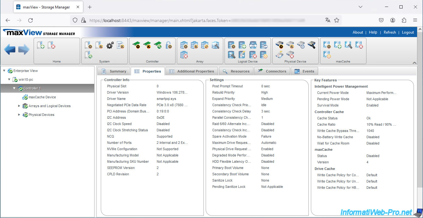
- Negotiated PCIe Data Rate: corresponds to the "Host Bus Type" and "Host Bus Link Width" data which has simply been merged since version 4 of maxView.
- PCI Address (Domain:Bus:Device:Function) : the PCI address where your Microsemi Adaptec SmartRAID controller is plugged into.
- I2C Address : address of the Inter-Integrated Circuit (I2C) slave. Computer bus connecting the microprocessor to different circuits.
- I2C Clock Speed : clock speed of this bus (I2C)
- I2C Clock Stretching Status : indicates whether this I2C bus is enabled or not
- NCQ : NCQ stands for Native Command Queuing and allows plugged-in SATA hard drives to arrange commands in the most suitable order for the best possible performance.
- Number of Ports : name of internal (Internal) and/or external (External) ports available on your Microsemi Adaptec SmartRAID controller
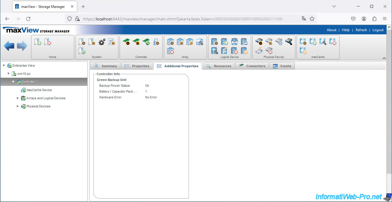
For the ASCM-35F battery, also called the Green Backup Unit, you will find :
- Backup Power Status : his status. Ok if it's fully charged or "Not Fully Charged" otherwise.
- Battery / Capacitor Pack Count : the number of batteries connected to your Microsemi Adaptec controller. In our case : 1.
- Hardware Error : indicates the type of hardware error that occurred with this battery (if any)
For the settings of your Microsemi Adaptec controller, you will find :
- Post Prompt Timeout : set the delay for F1 / F2 POST of the controller when starting the computer / server
- Rebuild Priority : in the event of a physical disk failure, indicates whether the rebuilding of a failed physical disk has a higher or lower priority compared to the other operations requested from the controller.
High means that the reconstruction will have priority over all the other operations that would be requested from your controller. This means that accessing and writing data to your RAID volumes may also be much slower until the rebuild is complete. - Expand Priority : same principle as for the above setting, except that it concerns the enlargement of an array of physical disks
- Advanced Statistics : if this setting is enabled, it allows you to see advanced statistics regarding your controller, hard drives, SSDs, logical drives, maxCache devices including virtual volumes and the maxCache container.
- Consistency Check Priority : background process that automatically checks the health of your hard drives to ensure that you can recover your data even if one of your hard drives fails.
To do this, this process checks that the parity data (if applicable) is still valid and that your hard drives don't have bad sectors. - Consistency Check Delay : determines how long the controller must be idle before this process checks the physical hard drives connected to the controller. This delay can be configured between 0 and 30 seconds, but 0 disables this verification process. Which is strongly discouraged.
- Parallel Consistency Check Count : determines the number of logical drives that can be checked simultaneously
- Raid 6/60 Alternate Inconsistency Repair Policy : repair policy only for RAID 6 and 60 which searches for an inconsistent strip and repairs it only on the affected disk
- Consistency Check Inconsistency Notify : indicates whether event notifications are enabled or not
- Spare Activation Mode : when this mode is configured to "Failure", the firmware is allowed to rebuild the failed physical disk on the physical disk configured as Spare in your array when a physical disk in the array fails or that its failure is predicted thanks to its SMART data. This reduces the time during which permanent data loss could have occurred.
- Maximum Drive Request Queue Depth : this controls the queue for cache writing and is mostly used to tune the performance of the controller for video applications (video editing)
- Monitor and Performance Delay : this controls the monitoring and analysis of controller performance for the same reason as the previous setting
- Physical Drive Request Elevator Sort : this controls the controller cache write elevator sorting algorithm for the same reason as before
- Degraded Mode Performance Optimization : this only concerns logical drives in RAID 5 configured in "Degraded" mode only.
Enabling this setting improves performance when a large number of reads are sent to hard drives.
Disabling this setting forces the controller to read data multiple times from the same hard drives.
This option is, once again, mainly used for video applications. - HDD Flexible Latency Optimization : enabling the Flexible Latency Scheduler (FLS) allows the controller to override input/output (I/O) priorities to prevent some hard drive access requests from time-out.
However, when this setting is disabled (or the controller doesn't support FLS), the controller reorganizes the requests to be sent to the hard disks to avoid physical back and forth of the read head in your hard disks as much as possible. - Primary Boot Volume : indicates which volume is set as the primary boot volume
- Secondary Boot Volume : indicates which volume is set as secondary boot volume
- Sanitize Local : determines the policy to apply to all connected physical SATA hard drives that support this feature.
- Pending Sanitize Lock : indicates which "Sanitize Local" policy will be applied after reboot in case you have just changed this setting and have not yet restarted your computer / server
For the Key Features, you will find :
- Intel Power Management : the current power mode, the one that will be used after restarting your computer if you have changed it (Pending Power Mode), as well as whether or not Survival mode is enabled
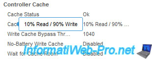
- Controller Cache : information about the controller cache :
- Cache Status : his status
- Cache Ratio : its ratio. In our case : 10% allocated to reading and 90% for writing
- Write Cache Bypass Threshold (KB) : the threshold in KB from which data will be written directly to the physical hard disks without going through the cache.
- No-Battery Write Cache : indicates whether or not the controller should enable write caching when there is no battery or when the battery fails. The recommended value is "Disabled" to prevent data in the cache from being lost if a power failure occurs at the wrong time.
- Wait for Cache Room : if this setting is enabled, it forces the controller to wait until there is room in the read/write cache when the read/write cache is full instead of bypassing it automatically to improve performance. - maxCache Status / Version : the status of the maxCache feature and its version. Note that maxCache requires a SSD to be plugged in and configured as a cache drive for you to use this feature.
- Drive Cache : Write Cache Policy informations for configured hard drives (Configured Drives), unconfigured drives, and Hard Drives available through the HBA Mode (HBA Drives) of the controller.
Since version 4, the information in the "Properties" tab has been divided into 2 tabs: "Properties" and "Additional Properties".
However, the information displayed is the same.
For the cache, it's in our case : 10% Read / 90% Write.
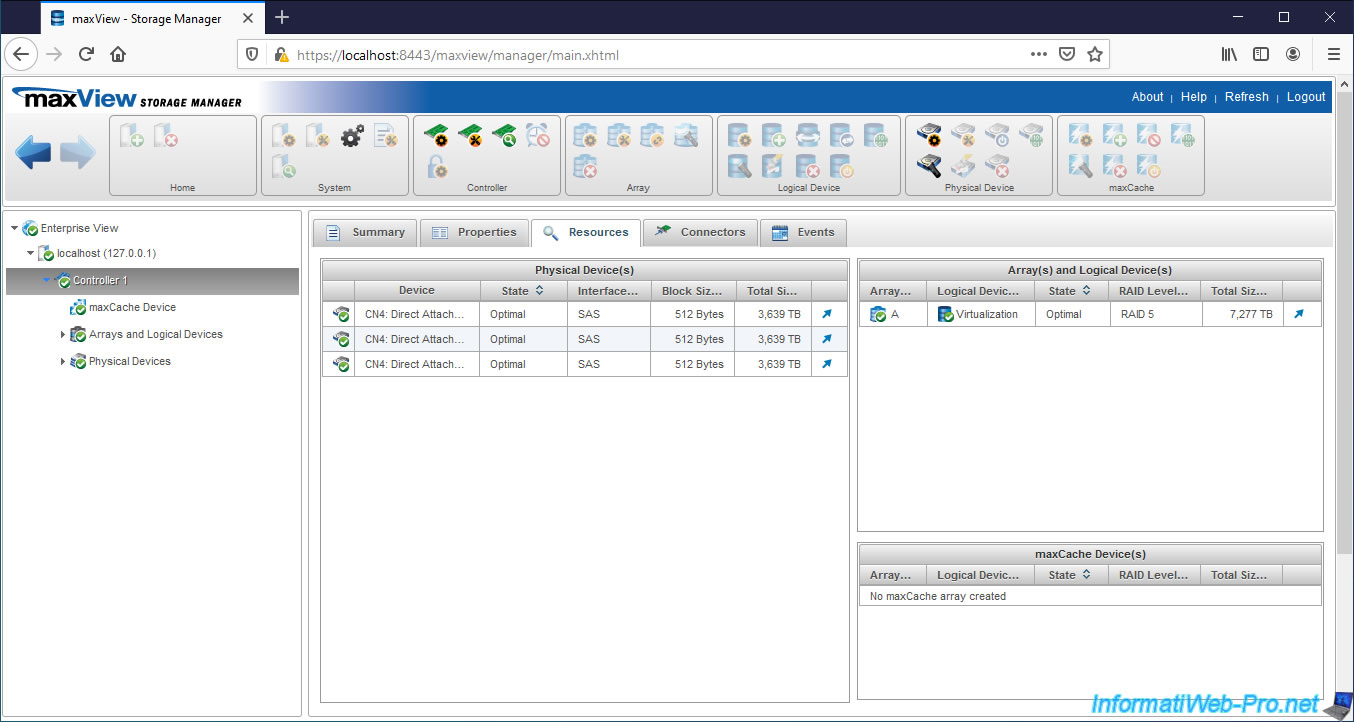
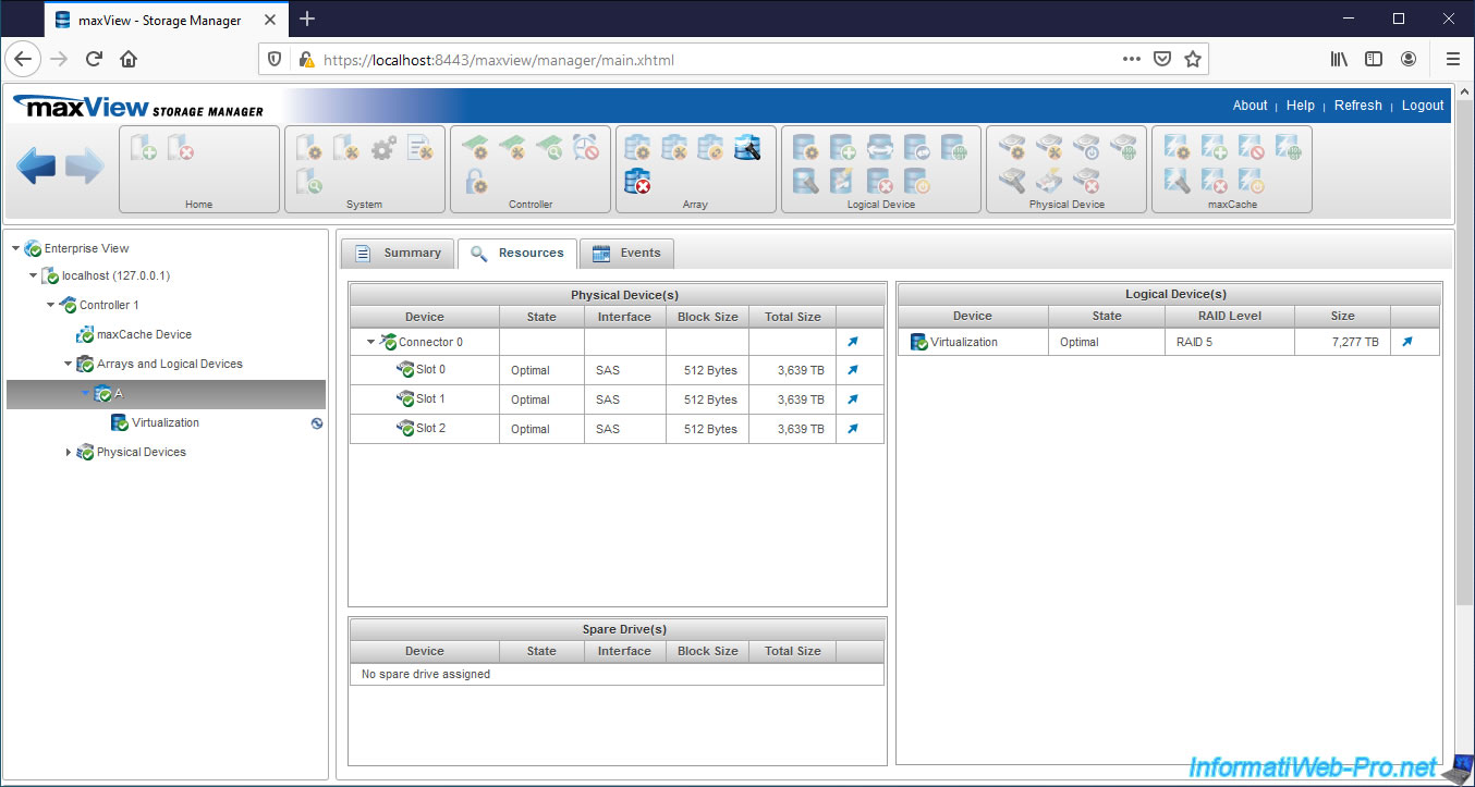
In the "Resources" tab of your Microsemi controller, you will find the list of :
- physical disks (hard disks and/or SSDs) with the number of the port to which they are connected, their status, the connection interface (SAS / SATA), the size of blocks used and the total size of each physical disk
- RAID volumes and logical drives created on your Microsemi SmartRAID controller with their names, statuses, chosen RAID level and total size of these
- disks configured to be used as a cache via the maxCache feature
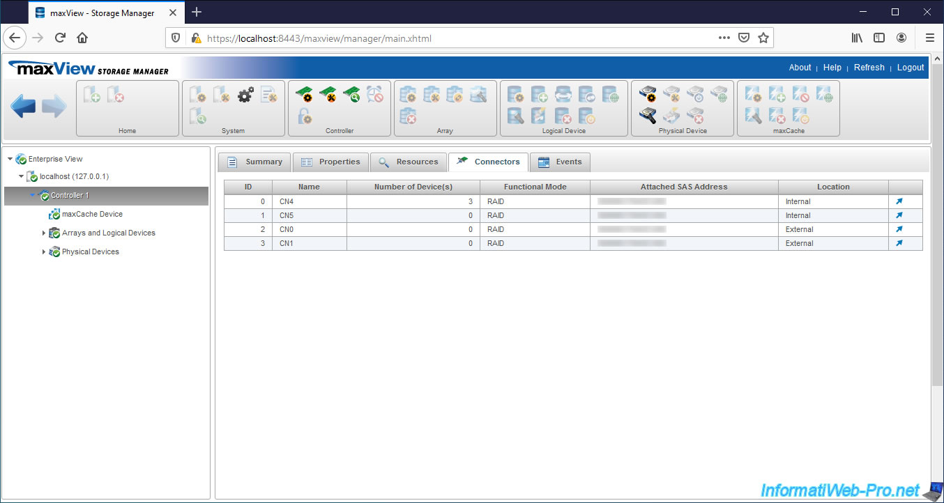
In the "Connectors" tab of your Controller, you will find the list of internal and external ports available on your Microsemi SmartRAID controller with :
- their names
- the number of hard drives and/or SSDs connected to it
- the functional mode of each port : RAID or HBA
- the SAS address that is assigned to each of these ports
- the location of these
So, we can easily see that the CN4 and CN5 ports of our Microsemi Adaptec SmartRAID 3154-8i8e controller are the 2 internal ports and the CN0 and CN1 ports are the external ones.
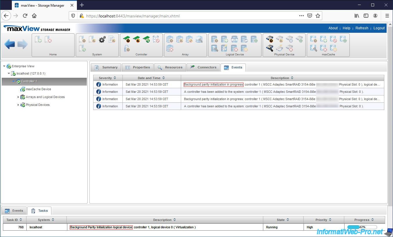
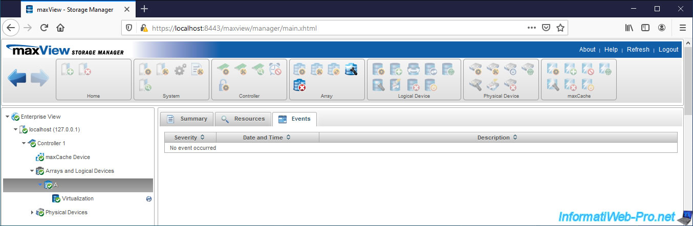
In the "Events" tab of your Microsemi controller, you will see the list of events concerning your Microsemi controller.
In our case, for example, we can see that parity initialization is in progress in the background on our MSCC Adaptec SmartRAID 3154-8i8e controller.
At the bottom of the page, in the "Tasks" tab, we can see the progress of this initialization : Background Parity Initialization logical device controller 1, logical device 0 (Virtualization) - 42%.
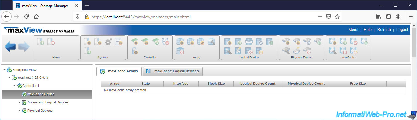
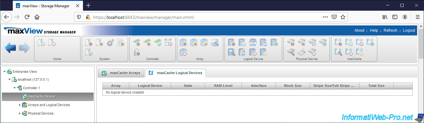
3.5. Information about maxCache devices
In the maxCache Device section, you will find the volumes and logical drives that you created and defined as cache devices.
These will be used by the maxCache feature to improve the performance of your RAID volumes.
In our case, we don't have one.
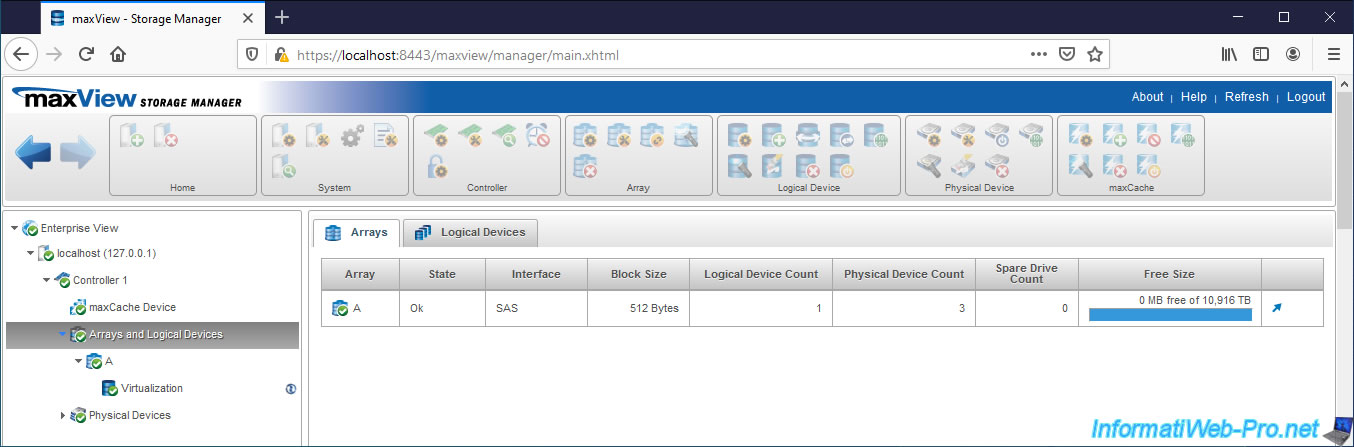
3.6. Information about your hard drive arrays and logical drives
In the "Arrays" tab, you will find the list of your hard disk arrays with :
- Array : their name. These are named automatically with the letters of the alphabet : A, B, C, ...
- State : their status
- Interface : the connection interface of your physical hard disks. Ex : SAS or SATA.
- Block Size : the size of blocks used
- Logical Device Count : the number of logical drives created on it
- Spare Drive Count : the number of hard drives configured as spare hard drives. A spare is used from the moment one of the hard disks in the array fails to automatically rebuild the data of the missing physical disk.
- Free Size : free space and total space available on this hard disks array
In the "Logical Devices" tab, you will find the list of logical drives created on your Microsemi controller with :
- Array : the name of the array where it's located
- Logical Device : its name
- State : its state
- RAID Level : the level of RAID used
- Interface : the connection interface (SAS or SATA) of the hard drives in the hard drives array
- Block Size : the size of blocks used
- Stripe Size/Full Strip Size : the size of each stripe (Stripe Size) and the combined size of these strips counting all the hard drives in the array (Full Stripe Size)
- Total Size : the storage size available on this logical device

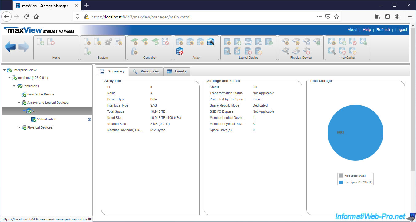
3.7. Information about a hard drives array
In the "Summary" tab, you will find information about the hard disks array (Array Info) selected on the left :
- ID : array ID from 0 to X
- Name : a letter of the alphabet from A to Z (A, B, C, ...)
- Device Type : Data if this hard disks array will be used for storage or Maxcache if it will be used as a cache
- Interface Type : connection interface of your hard disks. Examples : SAS or SATA.
- Total Space : total hard drives array size
- Used Size : size used on the hard drive array by logical devices
- Unused Size : unused size on the hard disks array
- Member Device(s) Block Size : maximum size of data blocks on hard disks that are part of this hard disks array
You will also find the settings and status of your hard drives array :
- Status : hard drives array status
- Transformation Status : indicates whether the array is being transformed or not
- Protected by Hot Spare : indicates whether the array is protected with Hot Spare that can be used hot (automatically in the event of a failure)
- Spare Rebuild Mode : indicates the type of spare for this array :
- dedicated : the hot spare can be assigned to one or more hard disk arrays and can protect any logical disk present on them
- auto replace : le hot spare est assigné à une grappe de disques durs spécifique et peut protéger n'importe quel disque logique présent sur celle-ci - SSD I/O Bypass : provides an optimized data path to high performance SSDs by overriding the RAID processor and sending data directly to the drives
- Member Logical Device(s) : number of logical drives that are members of this hard drives array
- Member Physical Device(s) : number of physical disks composing this array
- Spare Drive(s) : number of spare disks that can be used by this array to rebuild the missing physical disk (following a failure of one of the physical disks)
You will also find a graph on the right with the free space and the total space of the selected array.
In the "Resources" tab of your array, you will find the list of :
- hard drives therein, by connector
- logical disks created in this array
- hard disks available as Spares for this array
In the "Events" tab, you will find the events related to it.
Share this tutorial
To see also
-
RAID 4/20/2022
Adaptec maxView Storage Manager v3 - Create a RAID volume
-
RAID 4/8/2022
Adaptec maxView Storage Manager v3 - Download and boot on USB version
-
RAID 4/13/2022
Adaptec maxView Storage Manager v3 - Installation on Linux
-
RAID 4/15/2022
Adaptec maxView Storage Manager v3 - Manage an Adaptec SmartRAID controller on VMware ESXi 6.7
No comment