- RAID
- 20 April 2022 at 07:31 UTC
-


Although you can create an array and logical devices from the Microsemi Adaptec configuration tool available when your computer / server starts up, you can also do it via the "maxView Storage Manager" web interface.
Obviously, this technique is only possible if :
- an operating system is already installed on your computer / server
- you started your computer on a Windows To Go (Windows installation on an USB key)
- you booted from the USB version of maxView Storage Manager
- Create an array and a logical device from maxView Storage Manager
- Initialize the logical device in Windows
- Background logical device parity initialization
- Configure your logical device
1. Create an array and a logical device from maxView Storage Manager
Download and install maxView Storage Manager from the Microsemi site through the "Downloads" tab of your controller page.
If necessary, refer to our tutorial : Adaptec maxView Storage Manager v3 - Presentation.
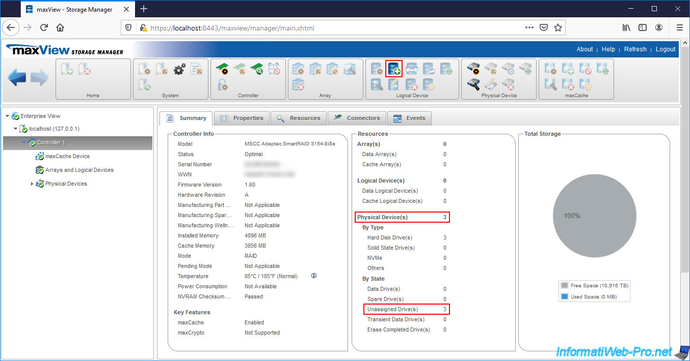
Then, access the "maxView Storage Manager" web interface and select your Microsemi Adaptec controller on the left.
As you can see, in our case :
- there is no array
- there is no logical device
- 3 physical disks (Physical Devices) are connected
- these 3 physical disks are not assigned (Unassigned Drives)
To create a new arrray and a new logical device in it, select your controller on the left, then click the "+" icon in the "Logical Device" section at the top of the page.
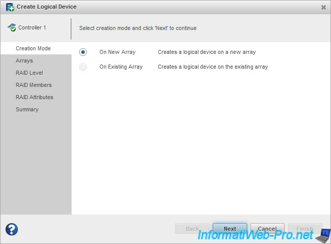
The "Create Logical Device" window appears.
Since we haven't created an array on our controller yet, we select "On New Array" to create a new array, then click Next.
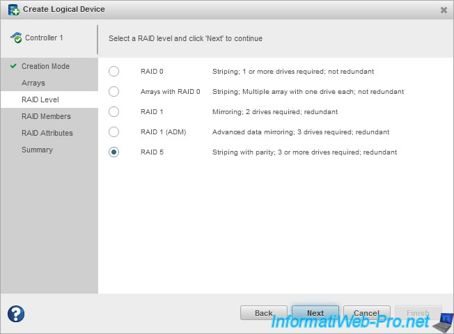
Select the desired RAID Level :
- RAID 0 : requires 2 hard drives and only improves performance by copying half of each data to each hard drive.
The loss of a hard drive will result in the loss of all data on that RAID array. - Arrays with RAID 0 : special mode based on RAID 0 which is not recommended for the security of your data
- RAID 1 : requires 2 hard disks and allows you to copy each data on the 2 hard disks at the same time. This level of RAID only improves the security of your data by supporting the loss of a hard drive.
- RAID 1 (ADM) : same as RAID 1, but with 3 hard disks. The only difference is that this RAID level supports the loss of 2 hard drives instead of 1.
- RAID 5 : requires 3 hard disks and allows to combine performance and security. This level of RAID supports the loss of a single hard drive.
In our case, we are going to create a RAID 5.
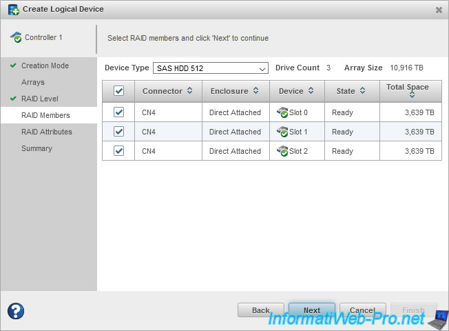
In the "RAID Members" step, select the hard disks that will be members of your array.
Now that your Array is defined, the wizard asks you to create your Logical Device.
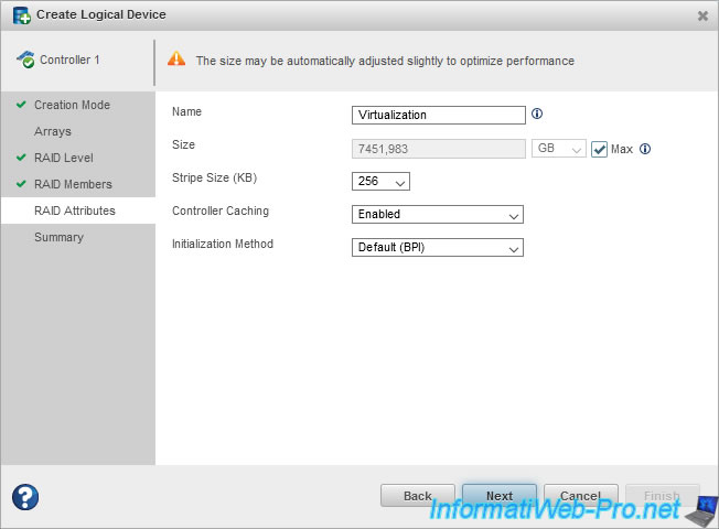
Specify :
- Name : a name to easily find it in Microsemi configuration tools (including : ACU and maxView)
- Size : its size. By default, the "Max" box is checked so that the logical device takes up all the available space on your array
- Stripe Size (KB) : stripe size on each hard drive. So, the amount of data written to one hard drive in the array before moving on to the next.
However, the value to choose depends on the number of physical disks and the RAID level selected previously. So, we recommend that you leave the default. - Controller Caching : allows you to enable or disable the use of read and write caches.
Warning : if you don't have a battery (eg ASCM-35F) connected to your Microsemi controller, we don't recommend that you enable it.
This is because in this case, if a power failure occurs while data is in the write cache, it will cause data loss.
Info : this doesn't apply to the read cache. - Initialization Method :
- Default (BPI) : allows you to instantly use your array, although its performance is reduced during parity initialization performed in the background.
- RPI : parity initialization will be done "offline" and your array will only be available when it's finished.
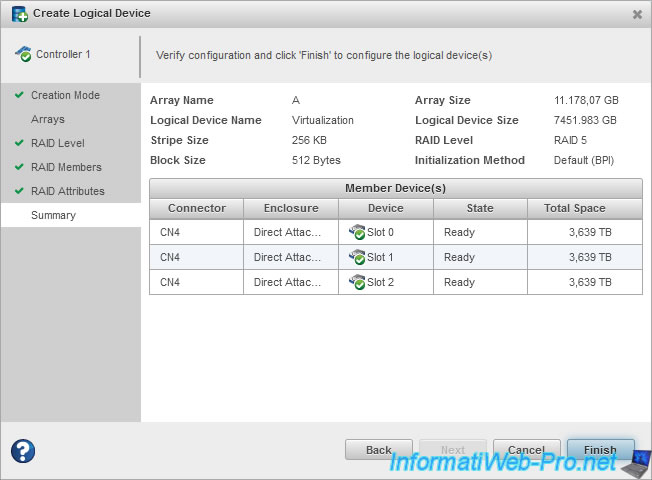
A summary of your Array and Logical Device configuration is displayed.
- Array Name : name automatically assigned to your array. Note that these are the letters of the alphabet (in order) : A, B, C, ...
- Logical Device Name : name of your logical device.
- Strip Size : stripe size on hard drives of the array
- Block Size : block size used on hard drives
- Array Size : your array size
- Logical Device Size : the loss of GB is due to the fact that with RAID 5, one of the 3 hard drives selected previously is used only for parity.
- RAID Level : RAID level selected for the array
- Initialization Method : initialization method chosen for parity initialization of your RAID array
Wait a bit.

And the "Create logical device operation successful" message will be displayed.
Wait again.

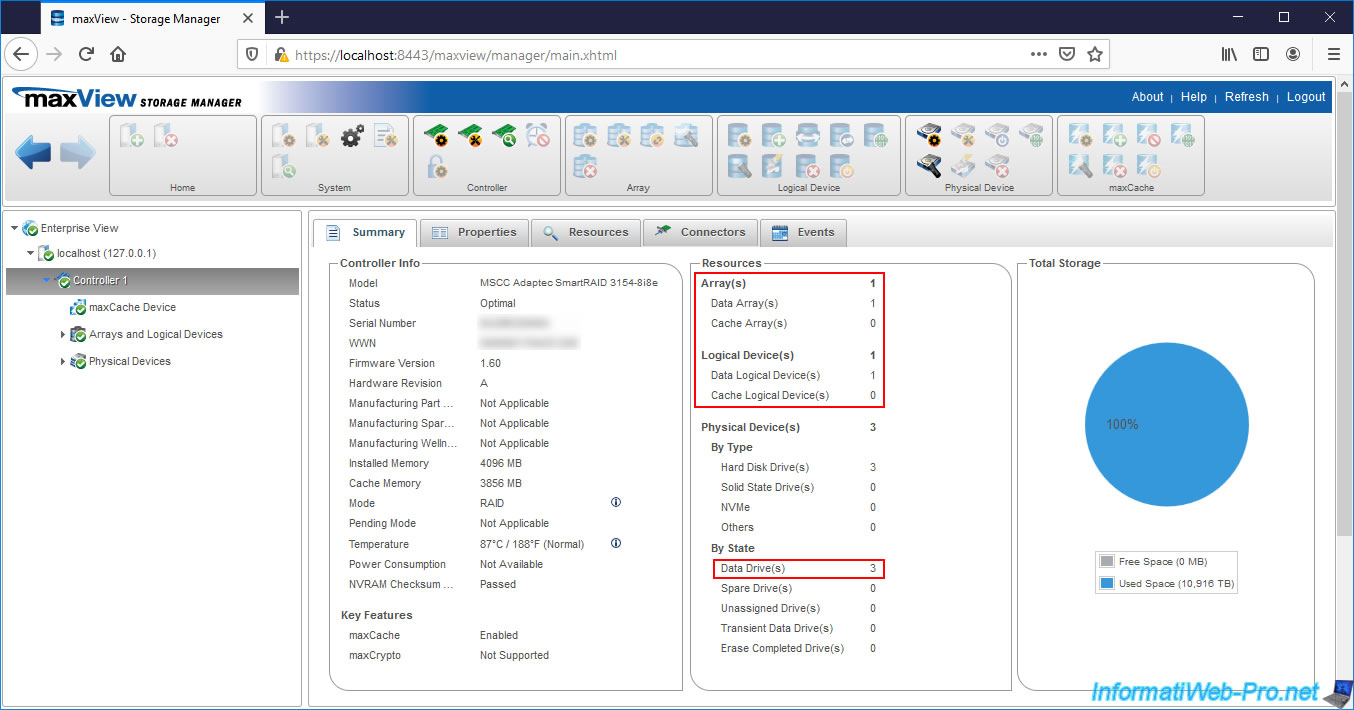
As you can see, our controller has :
- 1 array
- 1 logical device
- 3 physical disks which are used as Data Drives.
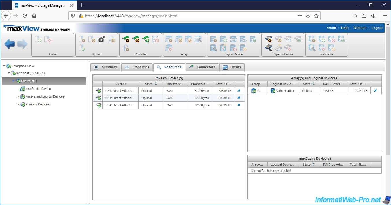
If you go to the "Resources" tab of your controller, you will see that there are :
- 3 physical disks with a SAS interface (connector)
- 1 array ("A")
- 1 logical device ("Virtualization") with a RAID level of "RAID 5"
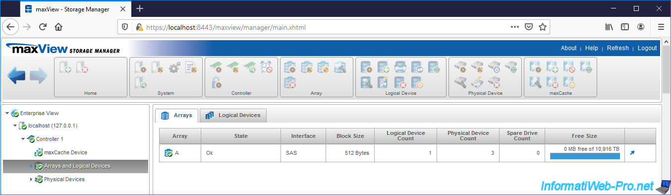
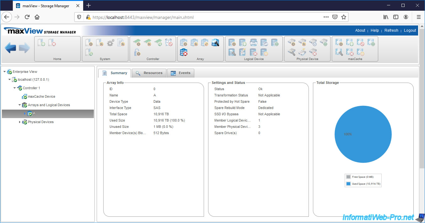
If you look in "Arrays and Logical Devices", you will find your "A" array.
If you go to the "Logical Devices" tab of this "Arrays and Logical Devices" section, you will find your logical device.
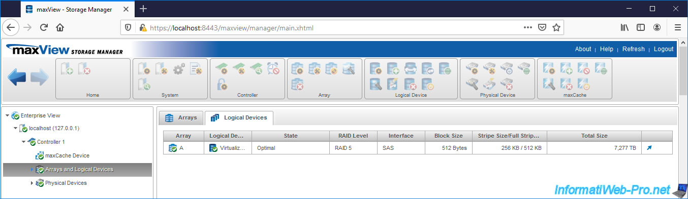
Our array contains 3 physical disks and 1 logical device.
Small difference compared to the configuration tool available at computer startup, when you create a logical device through maxView, you will probably see the value "Queued" for the line "Parity Initialization Status".
The parity initialization is therefore not yet started, but in the queue.
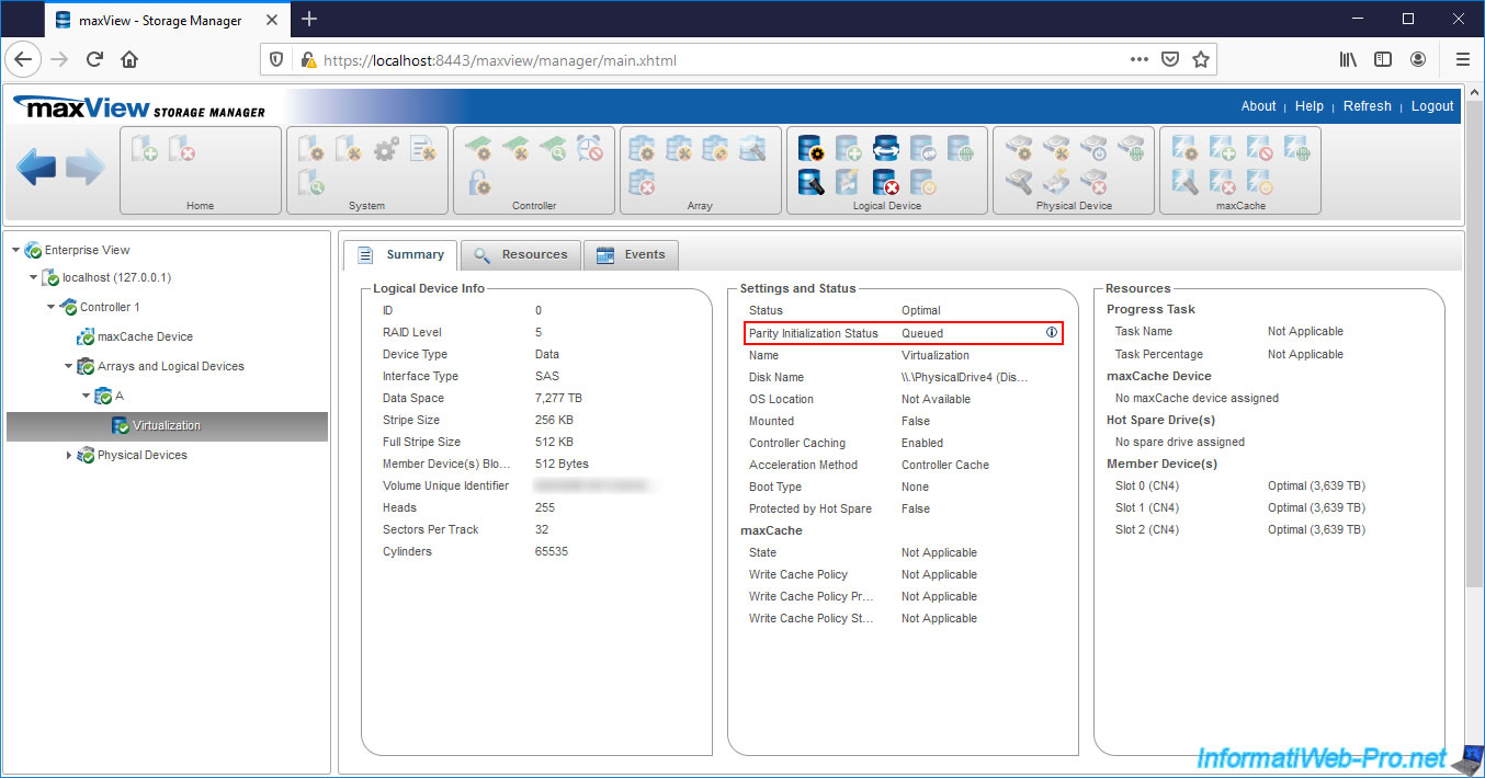
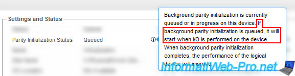
If you click on the little "i" next to this "Queued" status, you will see that maxView tells you that the background parity initialization (of your logical device) is queued and that this will start when I/O (inputs/outputs) are performed on it.
2. Initialize the logical device in Windows
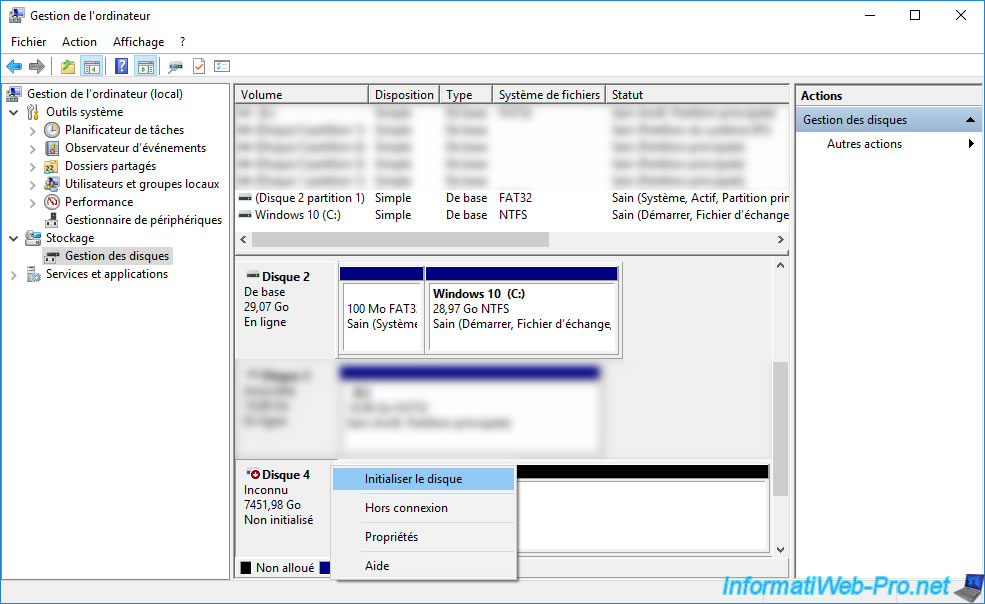
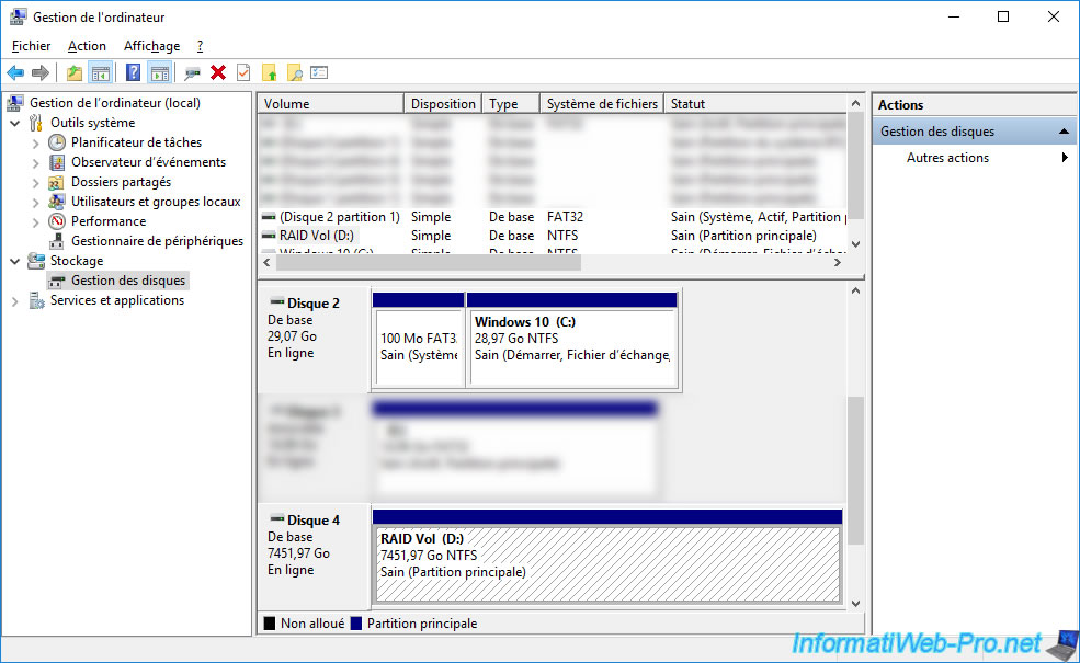
On Windows, open Disk Management and bring the disk online (if you haven't already).
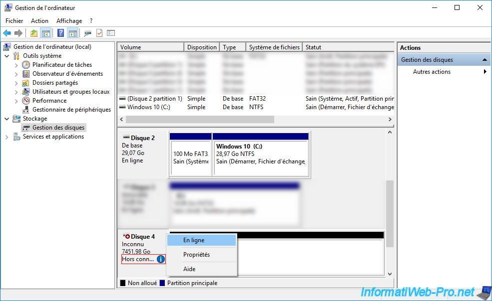
Then, right click "Initialize Disk" on it.
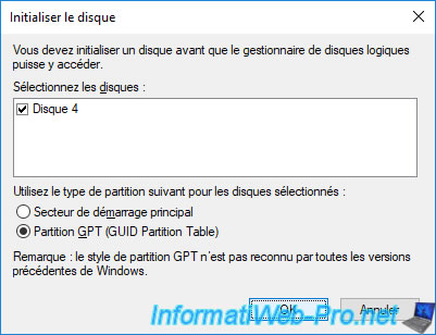
Select the type of partition to use on this disk :
- MBR (Master Boot Record) : corresponds to the MBR which doesn't support disks larger than 2TB and which limits you to 4 primary partitions
- GPT (GUID Partition Table) : allows you to boot in UEFI on this disk (if applicable) and to support disks of more than 2 TB (the limit being 9.4 Zo), but is not supported by all versions of Windows.
On Windows, GPT is supported from Windows 7 and UEFI booting to it will require a 64-bit (x64) version of Windows.
In our case, since our logical device is around 7 TB in size, we are forced to use GPT.
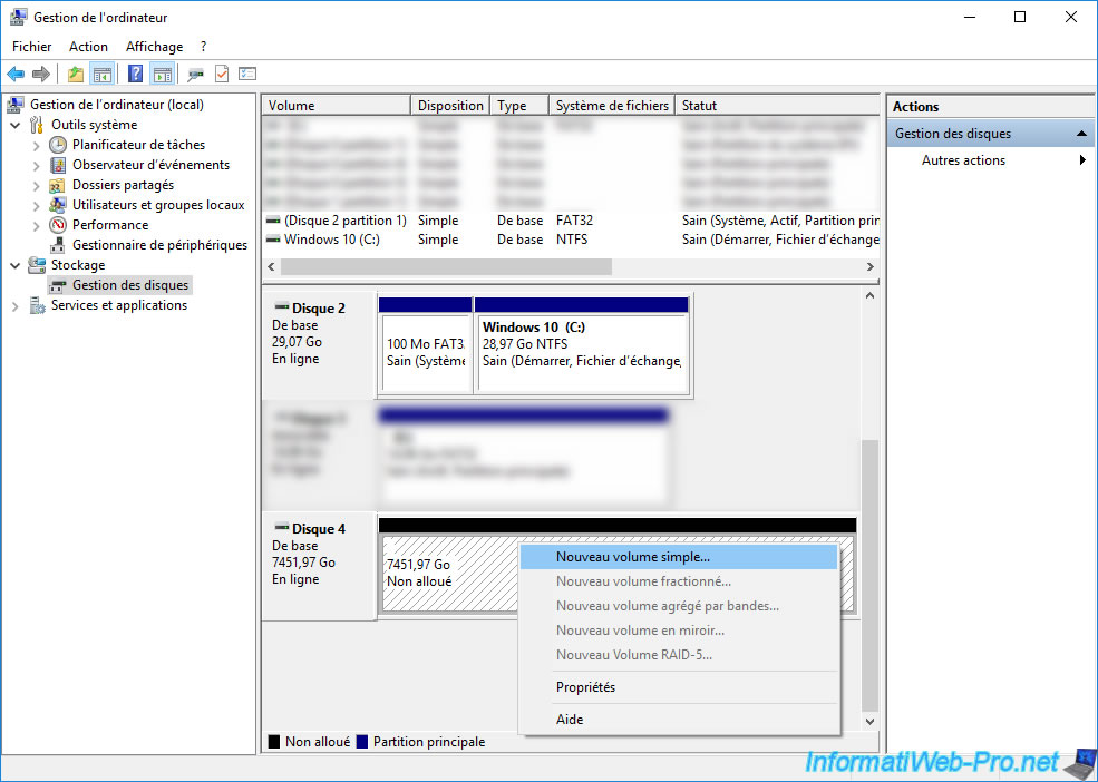
Now that the disk is initialized, you can partition it however you want.
To do this, right click "New simple volume".
The New Simple Volume Wizard appears.
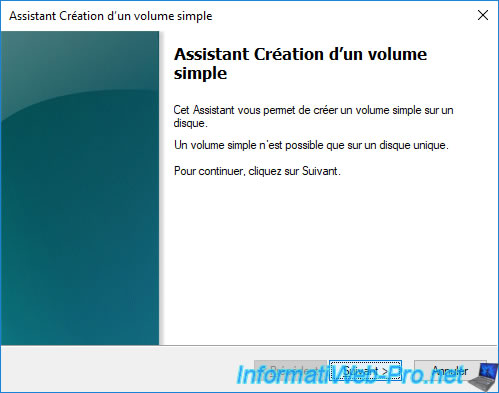
In our case, we will create only one partition (simple volume) to simplify the tutorial.
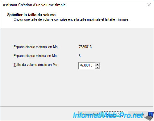
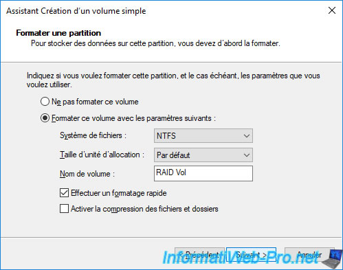
Enter a name.
In our case : RAID Vol.
Our logical device has a partition.
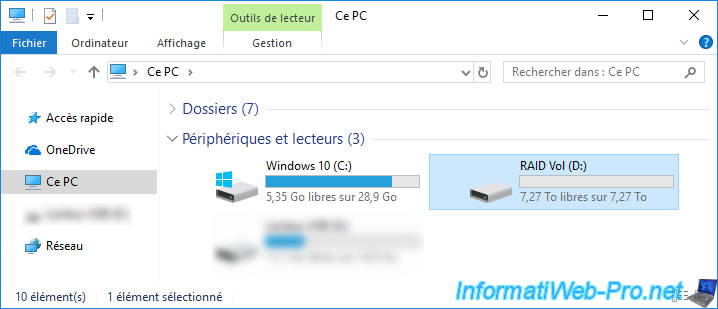
And it appears in the file explorer.
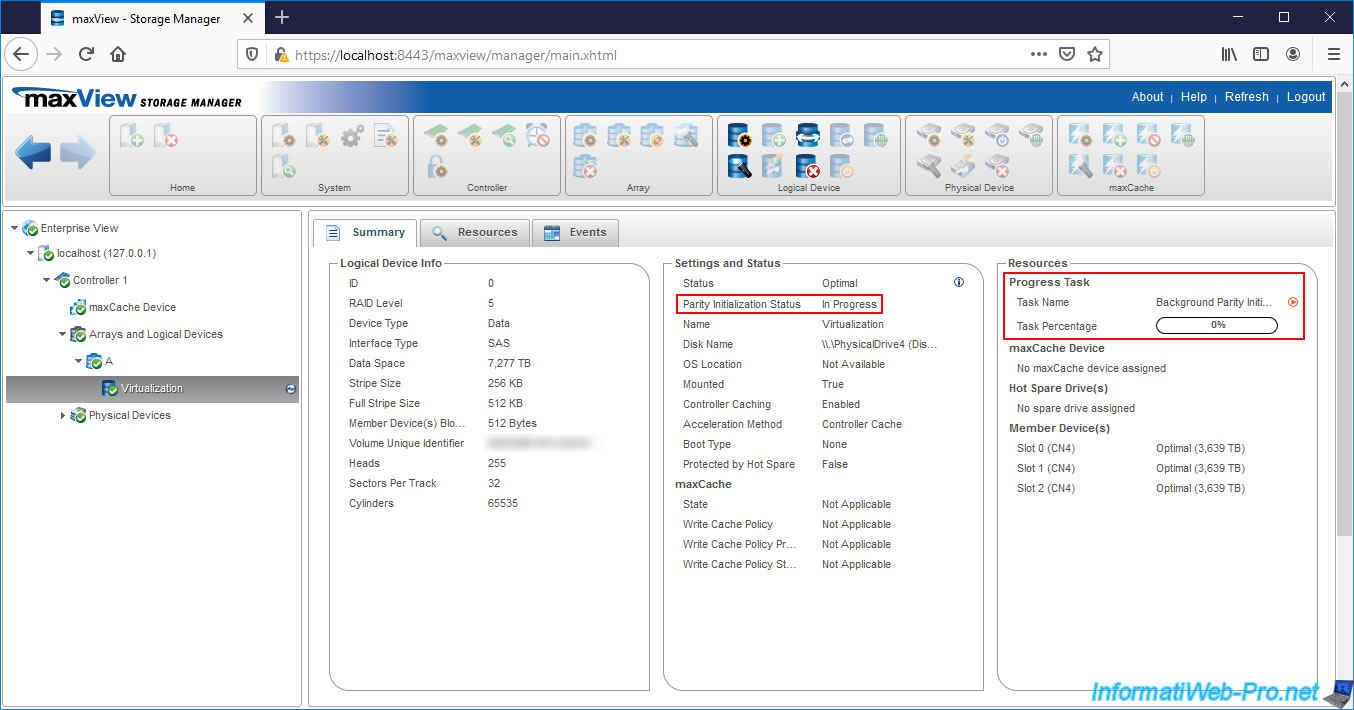
3. Background logical device parity initialization
Now that you have started using your logical device, go back to the "maxView" web interface and select your logical device.
As you can see, the Parity Initialization Status is now : In Progress.
In the right column, you will also see the progress of this background parity initialization process.
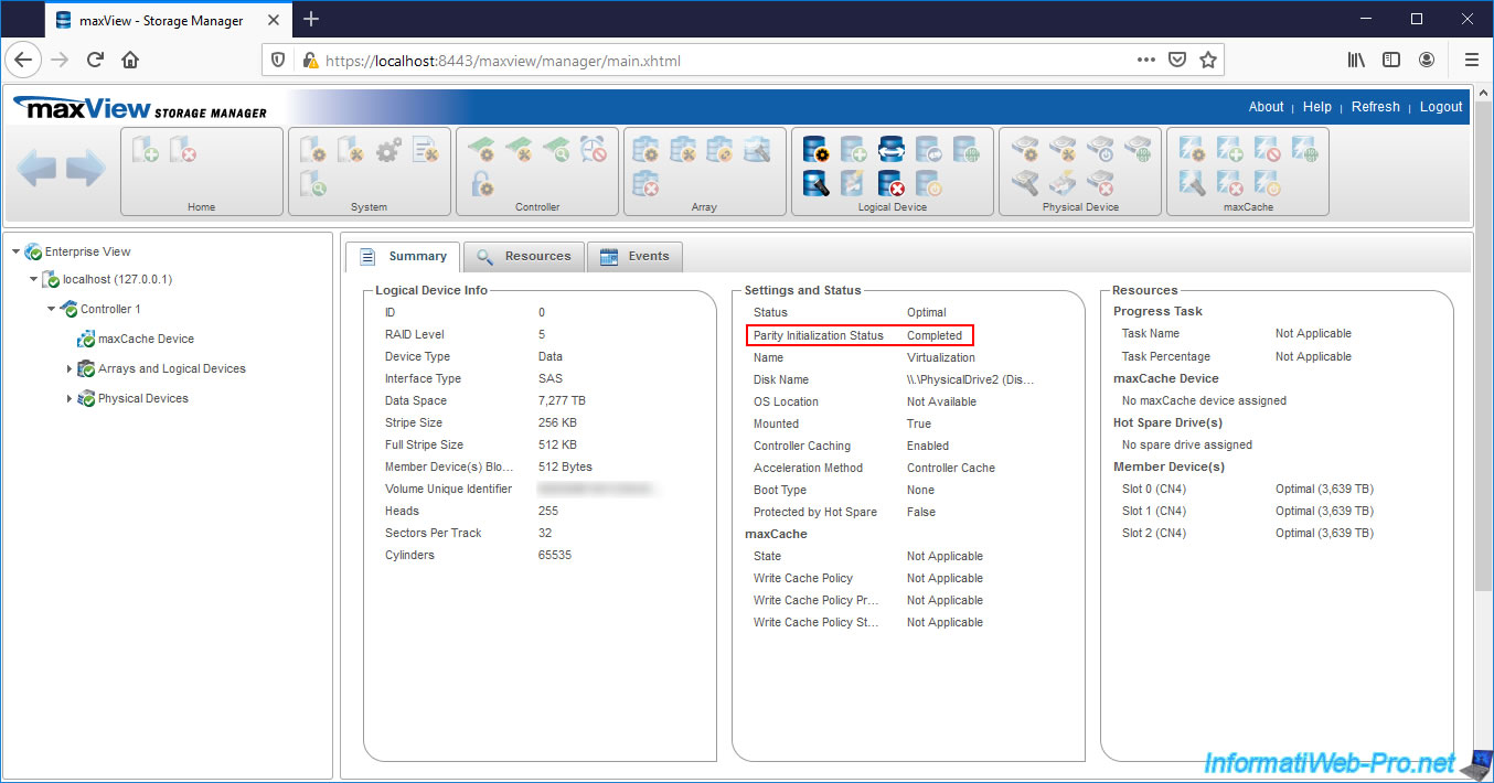
Once the parity of your logical device is initialized, the value of "Parity Initialization Status" will be : Completed.
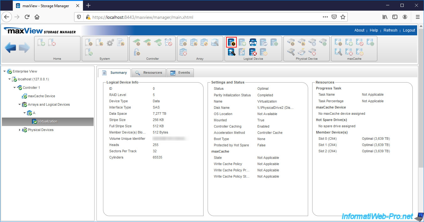
4. Configure your logical device
To configure the properties of your logical device, click on the 1st icon (framed in red on the image) located in the "Logical Device" block.
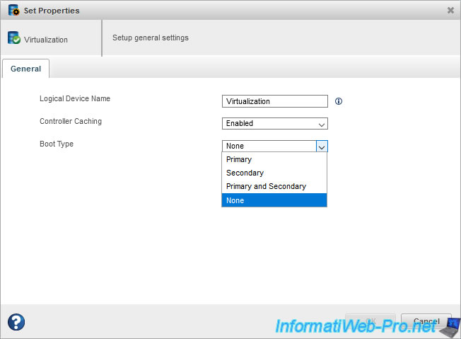
Here, you can :
- Logical Device Name : change its name
- Controller Caching : enable (Enabled) or disable (Disabled) the read and write cache
- Boot Type : enable or disable booting on this logical drive and set it as primary, secondary or both boot drive
Share this tutorial
To see also
-
RAID 4/8/2022
Adaptec maxView Storage Manager v3 - Download and boot on USB version
-
RAID 4/13/2022
Adaptec maxView Storage Manager v3 - Installation on Linux
-
RAID 4/15/2022
Adaptec maxView Storage Manager v3 - Manage an Adaptec SmartRAID controller on VMware ESXi 6.7
-
RAID 3/11/2022
Adaptec maxView Storage Manager v3 - Manage an Adaptec SmartRAID controller remotely
You must be logged in to post a comment