- Firewall
- pfSense
- 10 September 2025 at 13:07 UTC
-

- 1/2

In our "pfSense 2.6 - Create a VPN server (remote access) via OpenVPN (L3 mode)" tutorial, we explained to you how to allow your users to access the company network securely via an OpenVPN server created under pfSense.
However, it was an L3 tunnel (which is what is used most of the time). OpenVPN therefore used another subnet for its tunnel.
If you want your users connected via the VPN to be on the same subnet as the machines present in the company, you must configure OpenVPN to use "tap" (L2 connectivity) instead of "tun" (L3 connectivity) .
Note that in the case of "tap" (L2 connectivity), there is no longer a subnet used for the VPN tunnel.
IP addresses assigned to users connected via the VPN will therefore receive an IP address from the DHCP server of your company's LAN network (usually).
Important : to follow this tutorial, you must first follow our previous tutorial (cited above) up to and including step "7.1 Install the OpenVPN Client Export package".
Note that the subnet to use in the "Tunnel Network" box when following our previous tutorial is required by the OpenVPN wizard. Although you will then remove it in the tutorial below. So temporarily indicate a fictitious subnet that does not conflict with the subnets used by pfSense in your case.
- Change OpenVPN server mode to "tap" (L2) instead of "tun" (L3)
- Assign the OpenVPN server virtual interface as the OPT1 logical interface
- Enabled the created OPT1 logical interface
- Create a bridge between the VPN tunnel and the LAN network
- Export configuration for OpenVPN client
- Install the OpenVPN client
- Test the network connection between the OpenVPN client and the LAN network
- Check OpenVPN tunnel status
- Add the OpenVPN widget to the pfSense dashboard (optional)
1. Change OpenVPN server mode to "tap" (L2) instead of "tun" (L3)
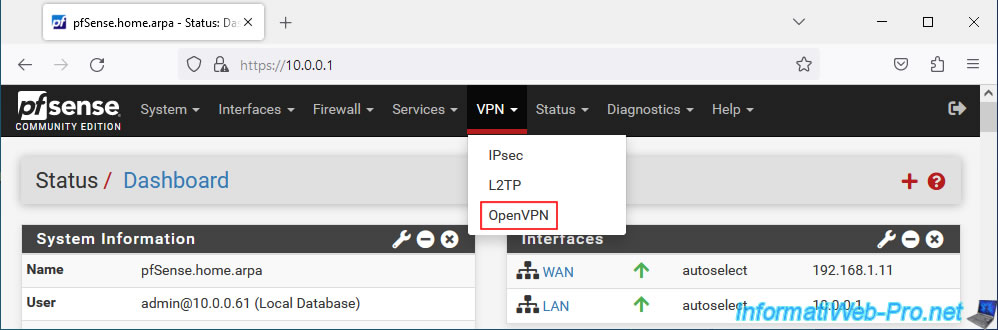
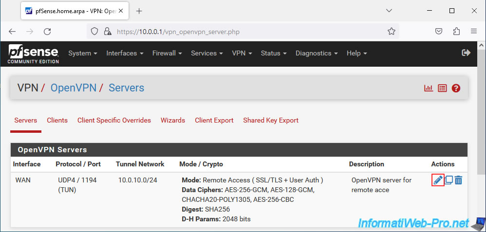
To get started, go to: VPN -> OpenVPN.
Click on the small pencil to the right of your OpenVPN server.
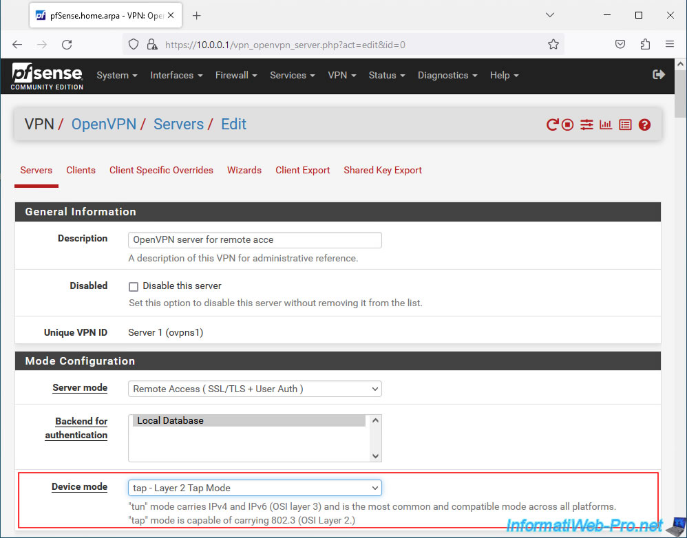
In the "Configuration Mode" section, change the value of the "Device mode" parameter to "tap - Layer 2 Tap Mode".
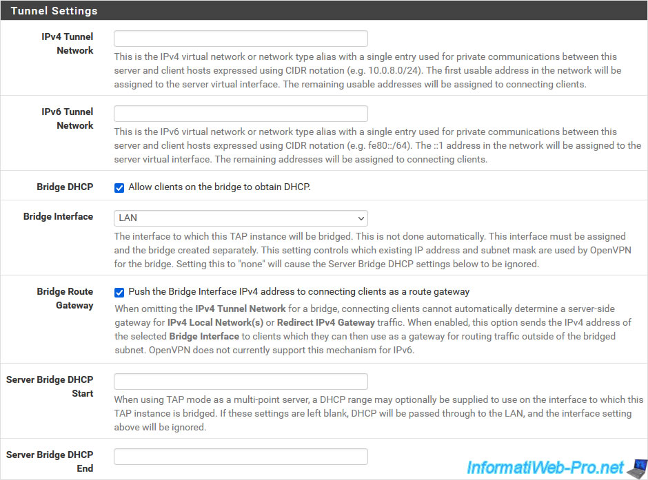
In the "Tunnel Settings" section, configure these settings:
- IPv4 Tunnel Network: remove the value you indicated previously.
Indeed, when OpenVPN operates in "tap" (L2) mode, there is no longer a subnet for the VPN tunnel. - IPv6 Tunnel Network: same, the box must be empty.
- Bridge DHCP: check the box "Allow clients on the bridge to obtain DHCP" so that clients who connect to your OpenVPN server automatically receive an IP address from the DHCP server on your LAN network, by default (or the one indicated via the parameter following "Bridge Interface", if you change it).
- Bridge Interface: indicates to which pfSense network users connected via OpenVPN will be connected.
In most cases, you will connect them to the pfSense LAN network.
Note: as indicated by pfSense, a bridge will have to be created manually to connect the interface of this OpenVPN server to the interface selected here (in our case: LAN).
But, you will see how to do it in the rest of this tutorial. - Bridge Route Gateway: for users connecting to your OpenVPN server to be able to access LAN network resources, you must check the box "Push the Bridge Interface IPv4 address to connecting clients as a route gateway".
Otherwise, the OpenVPN client will show you a "failed to parse/resolve route for host/network" warning and you will not have access to any machine on the LAN network. (Even pfSense will not be accessible.) - Server Bridge DHCP Start/End: these settings are optional and allow you to specify a different IP address range to be distributed to users connecting through an OpenVPN client.
So, although they will be on the same network, you can more easily filter network connections via the firewall thanks to the different IP address ranges defined for the LAN clients of the wired network and those connected via the VPN, if you wish it.
Source : Tunnel Settings | pfSense Documentation.
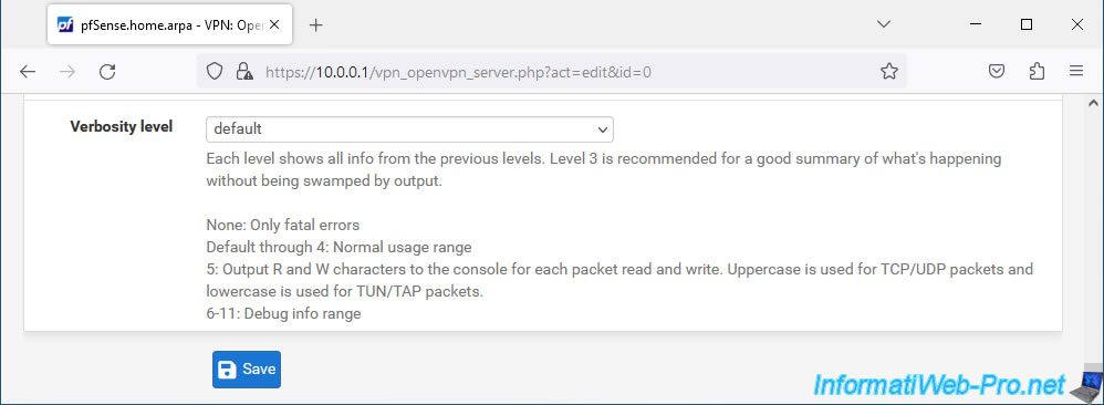
At the bottom of the page, click Save.
2. Assign the OpenVPN server virtual interface as the OPT1 logical interface
To create the bridge requested by pfSense for this L2 mode, you must first assign the virtual interface of your OpenVPN server as a logical interface (default: OPT1).
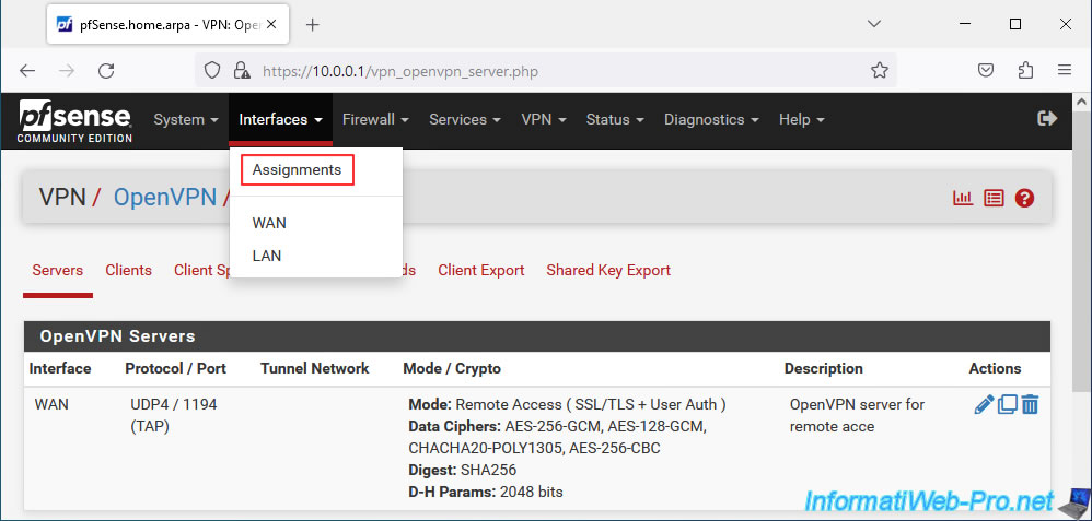
To do this, go to: Interfaces -> Assignments.
In the "Interface Assignments" tab, you will see that a new network port is available (Available network ports).
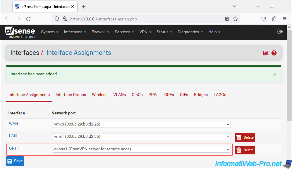
Select the port "ovpns1 (OpenVPN server for remote access)" displayed and click: Add.
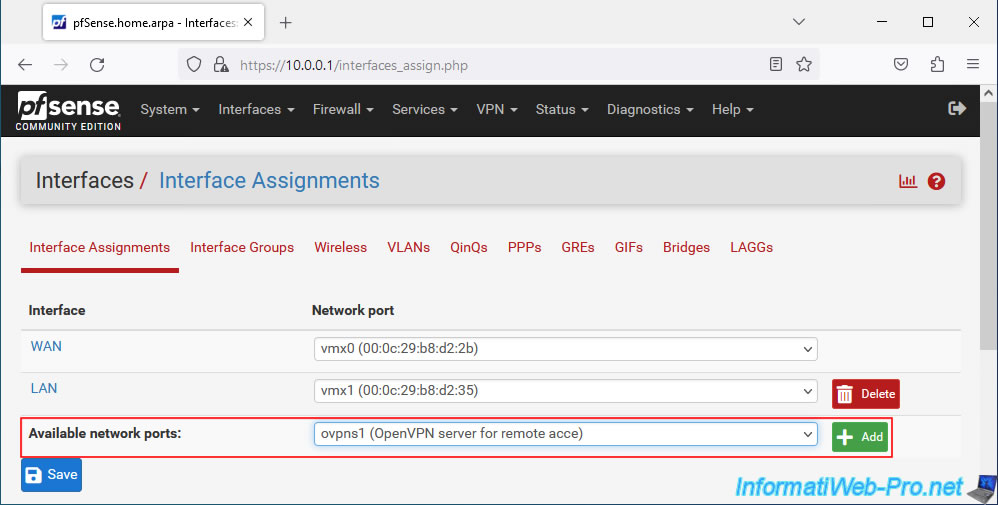
In our case, a new logical interface "OPT1" appears for our virtual interface "ovpns1...".
3. Enabled the created OPT1 logical interface
Now that your OpenVPN server's virtual interface has been assigned as logical interface "OPT1", you must activate this new logical interface in order to use it.
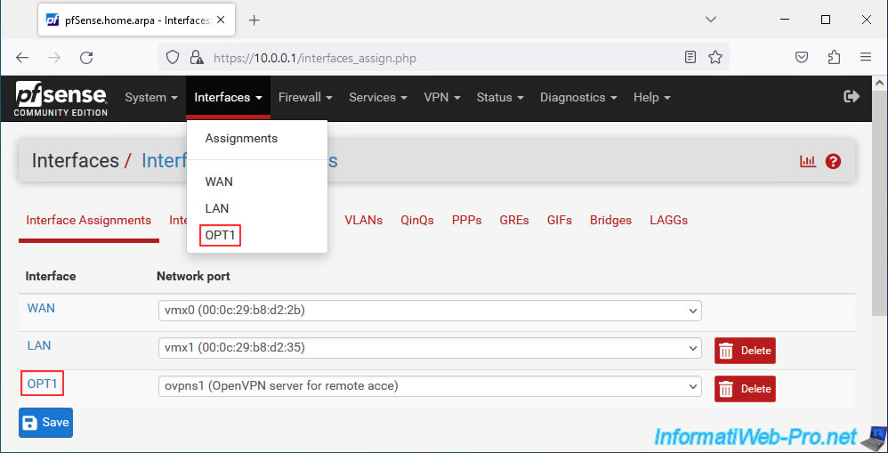
To do this, go to "Interfaces -> OPT1" or click on its name (in the "Interface Assignments" tab where you are currently).
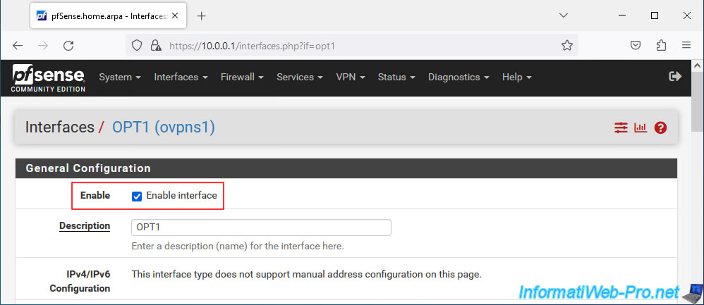
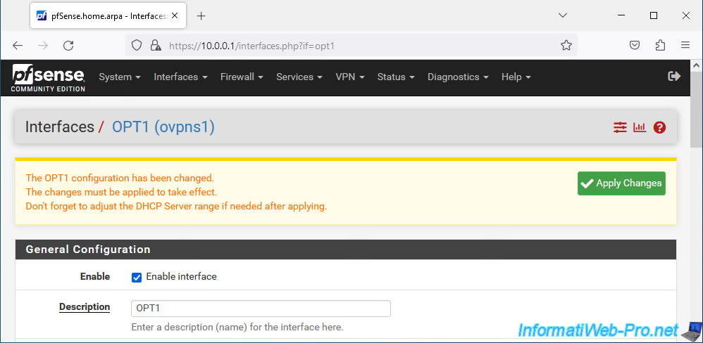
Check the "Enable interface" box.
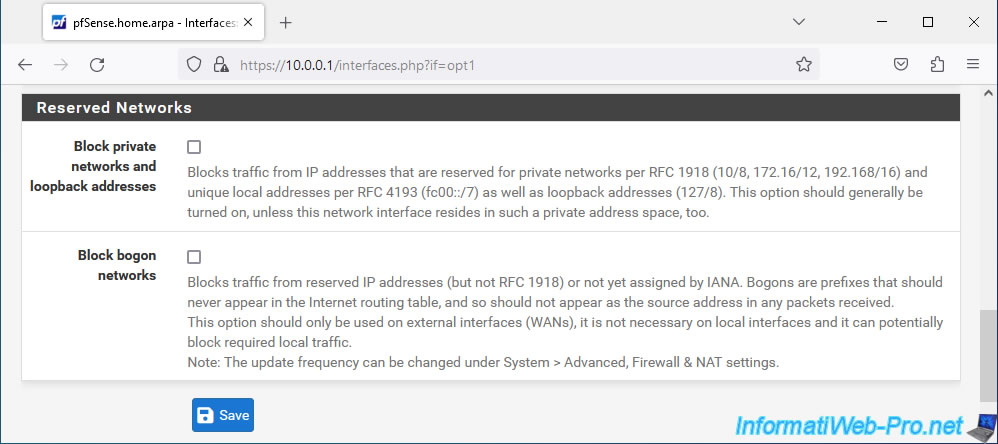
At the bottom of the page, click on: Save.
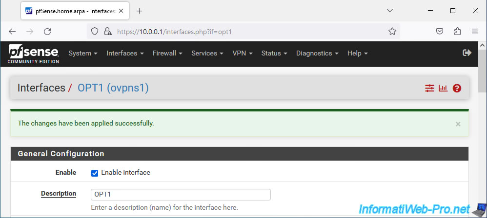
At the top of the page, click: Apply Changes.
Your OPT1 interface corresponding to your OpenVPN server is enabled.
4. Create a bridge between the VPN tunnel and the LAN network
So that users connected to your OpenVPN server can communicate transparently with machines physically connected to the LAN network, you must create a bridge between the logical interface "OPT1" (which corresponds to the virtual interface of the OpenVPN server) and the logical interface "LAN".
To do this, go to: Interfaces -> Assignments.
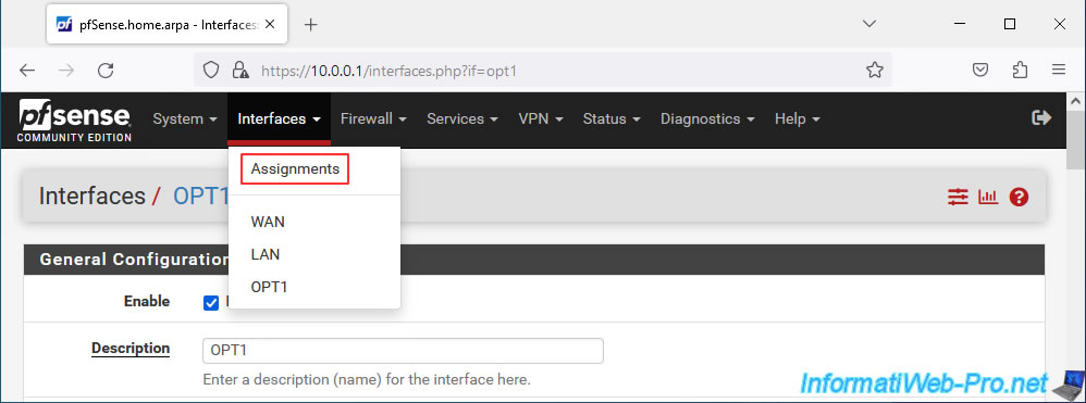
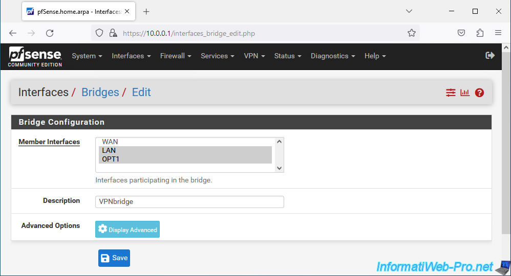
In the "Bridges" tab, click: Add.
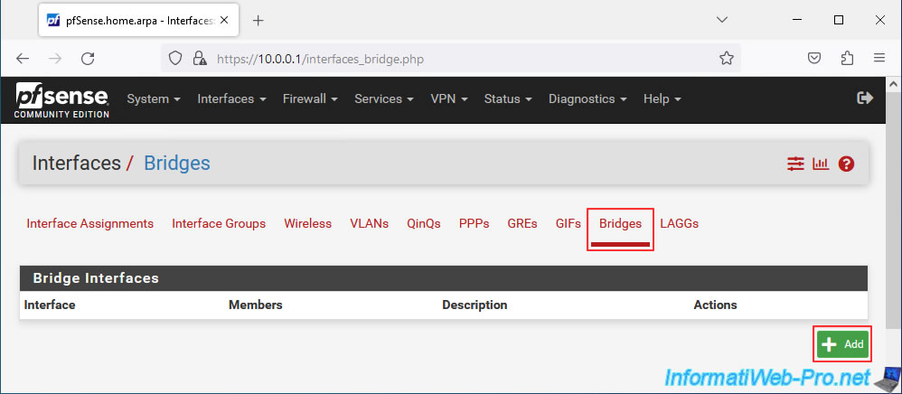
Select the "LAN" and "OPT1" interfaces (holding down CTRL when clicking on their names to select several).
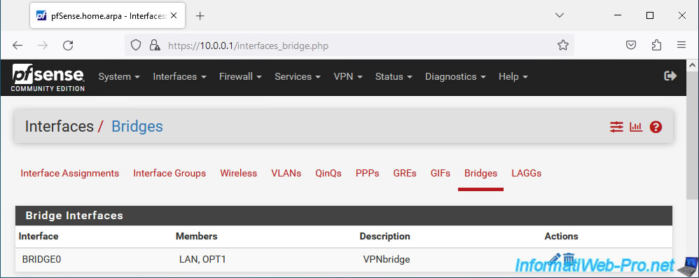
Provide a description for information purposes if you wish, then click: Save.
The network bridge appears, by default, under the name "BRIDGE0".
Source : Bridging OpenVPN Connections to Local Networks | pfSense Documentation.
Share this tutorial
To see also
-
Firewall 9/3/2025
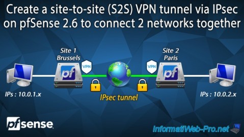
pfSense 2.6 - Create a site-to-site (S2S) VPN tunnel via IPsec
-
Firewall 9/17/2025
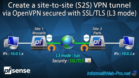
pfSense 2.6 - Create a site-to-site (S2S) VPN tunnel via OpenVPN secured with SSL/TLS (L3 mode)
-
Firewall 8/29/2025
pfSense 2.6 - Implement Multi-WAN (Dual-WAN)
-
Firewall 8/20/2025
pfSense 2.6 - Monitoring via SNMPv3 and Zabbix 6
You must be logged in to post a comment