Create a site-to-site (S2S) VPN tunnel via IPsec on pfSense 2.6 to connect 2 networks together
- Firewall
- pfSense
- 03 September 2025 at 07:43 UTC
-

- 4/5

2.3. Configure phase 2 of the IPsec tunnel on site 2 (Paris)
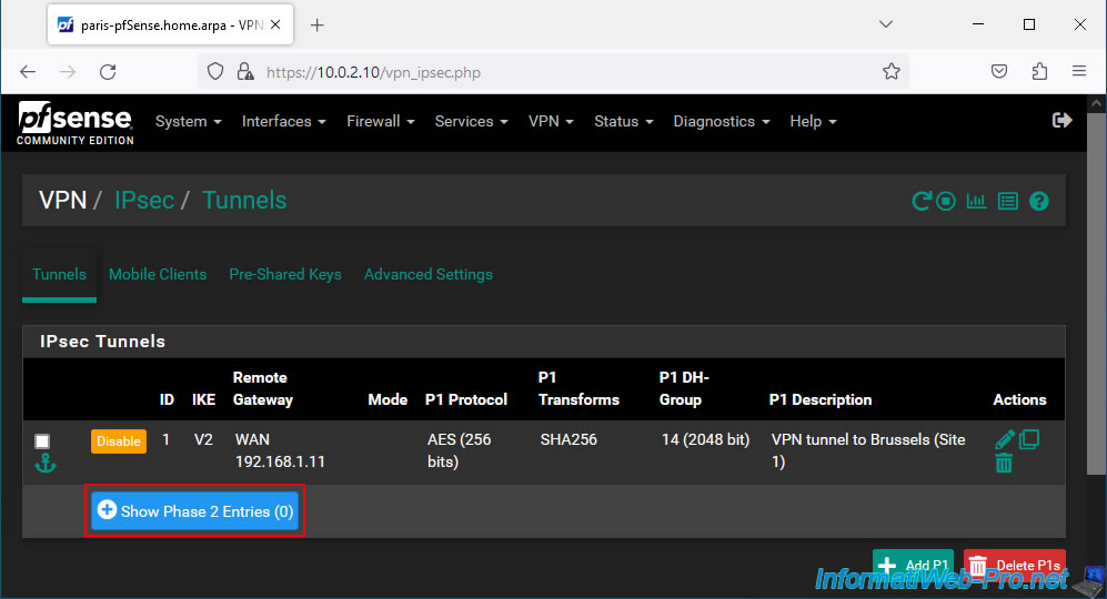
As on the other site, you must add a P2 tunnel to your P1 IPsec tunnel.
To do this, click on: Show Phase 2 Entries.
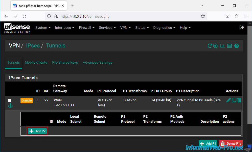
Then, click on: Add P2.
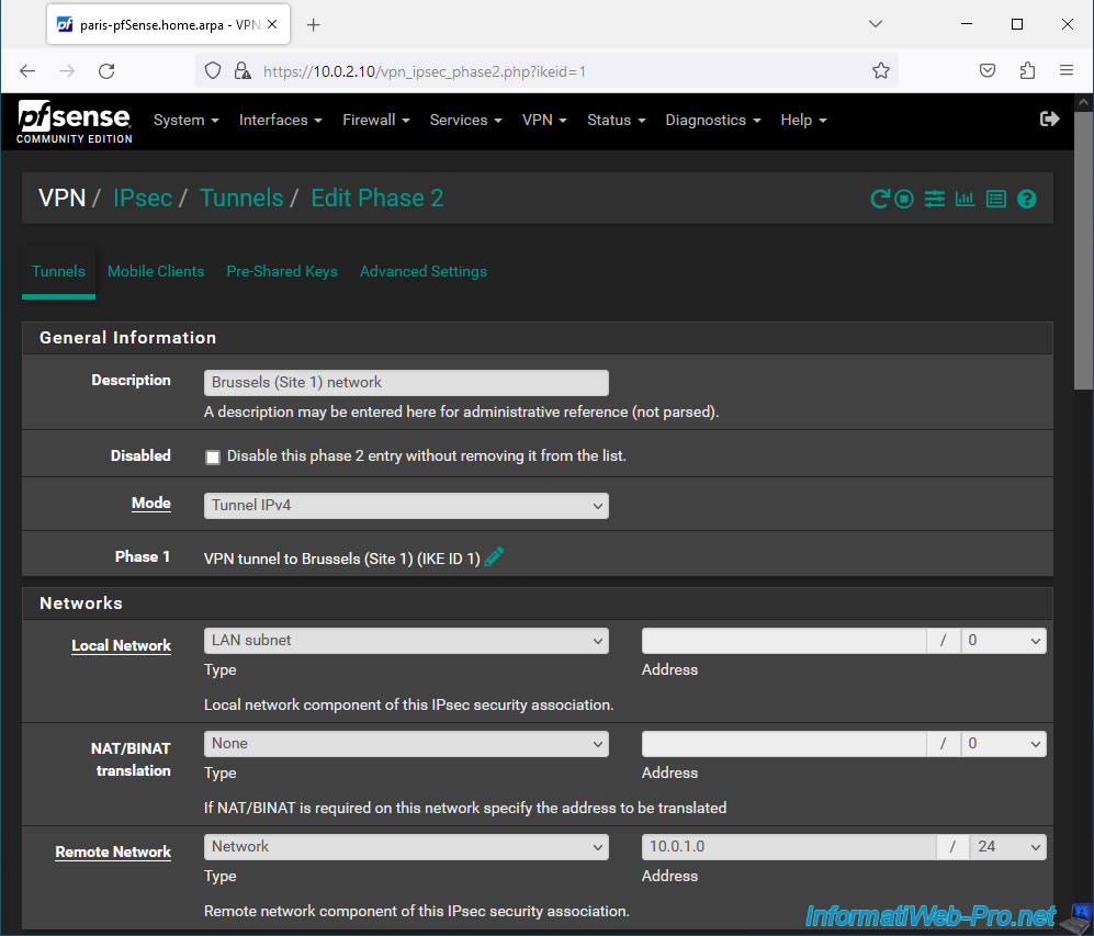
On the "Edit Phase 2" page, indicate this:
- Description: Brussels (Site 1) network. Given that this P2 tunnel will allow computers and servers in Paris to access the resources of site 1 (Brussels).
- Mode: IPv4 tunnel. Allows you to connect your 2 IPv4 networks.
- Local Network: LAN subnet. Corresponds to the network used on your site 2 which in our case is "10.0.2.0 / 24".
- Remote Network: select "Network" and indicate the network used on the remote site (in other words: site 1 (Brussels)).
In our case, the network used on site 1 (Brussels) is "10.0.1.0 / 24".
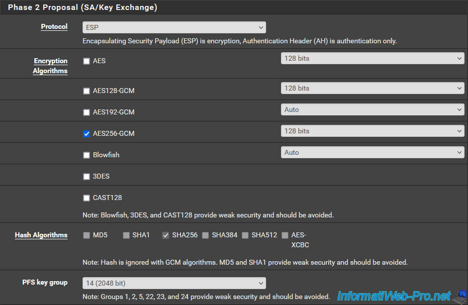
Important : for the exchange of keys, you must indicate exactly the same parameters as for the P2 tunnel created on the other peer (pfSense machine).
To know :
- Protocol: ESP. To benefit from encryption.
- Encryption Algorithms: preferably "AES256-GCM" with a key size of 128 bits or use "AES" with a key size of 256 bits.
- Hash Algorithms: in the case of "AES-GCM", the boxes will be grayed out. But if you are using AES, then select SHA256.
- PFS key group: 14 (2048 bit). Default value.
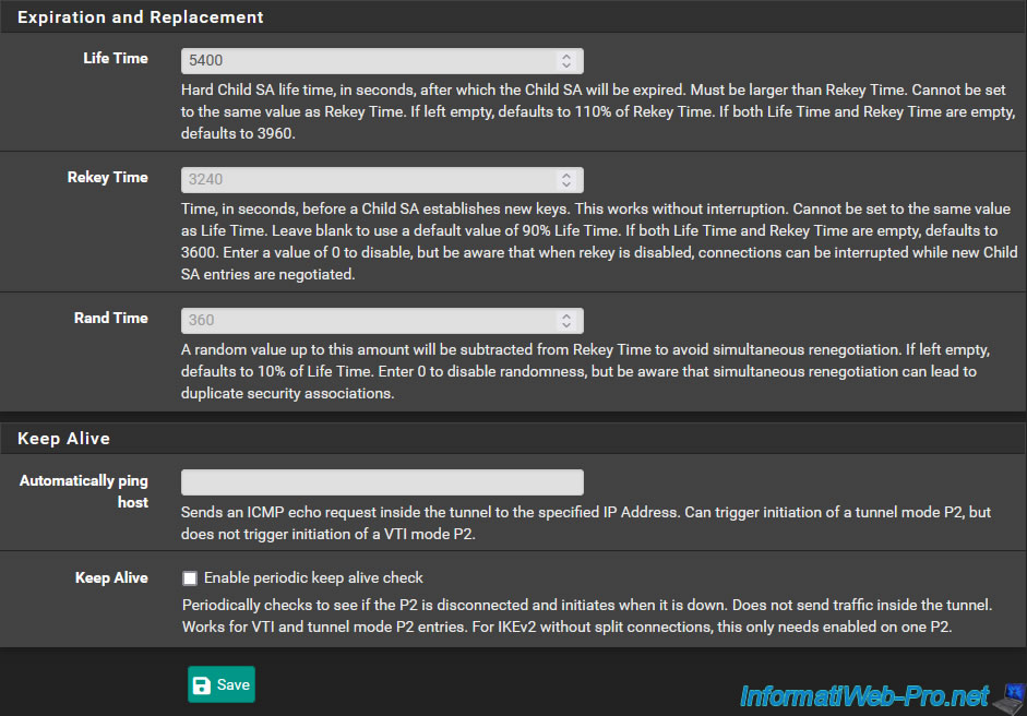
Important : to prevent this P2 tunnel from expiring at the same time on both sides, you must indicate a 10% higher value for its Life Time compared to the value configured on the other peer .
Which gives "5400" given that the other peer was using the value "3600".
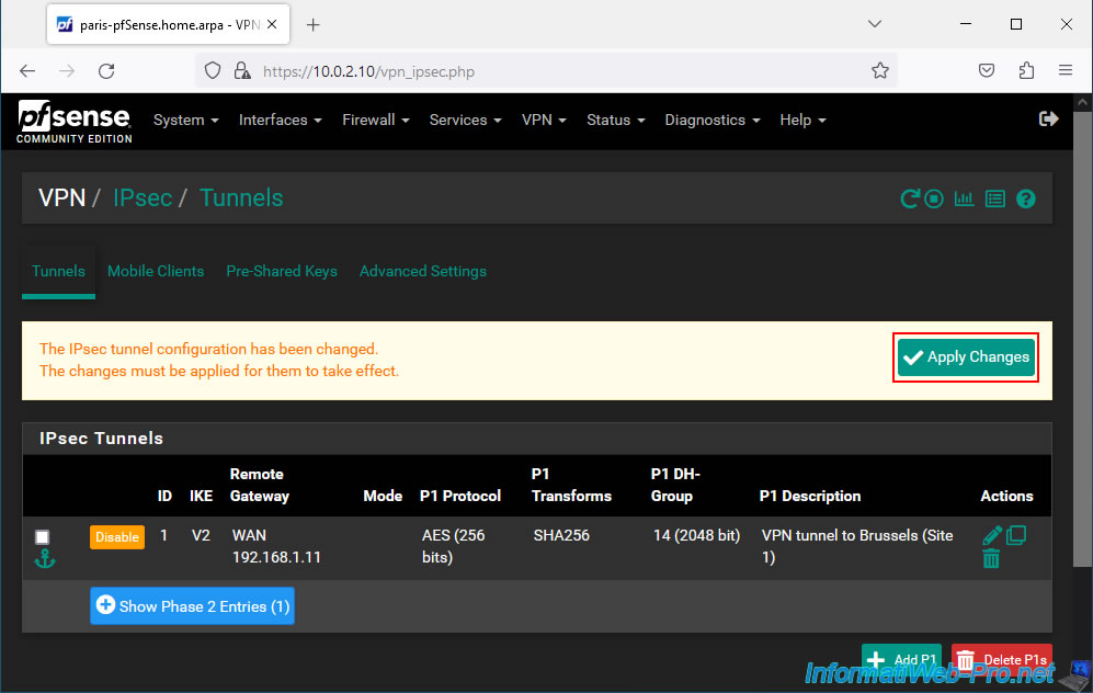
Click Save.
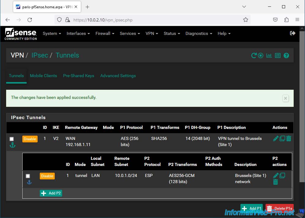
Click: Apply Changes.
Your P2 tunnel has been created.
2.4. Allow IPsec traffic coming from site 1 (Brussels) in the pfSense firewall
For computers and servers at Site 2 (Paris) to access resources at Site 1 (Brussels), you must allow IPsec inbound traffic to Site 1.
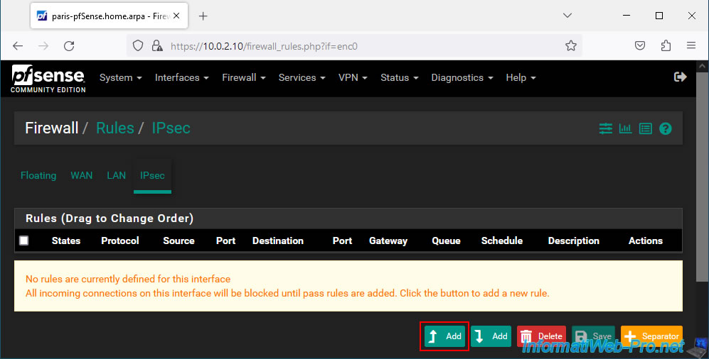
To do this, go to: Firewall -> Rules.
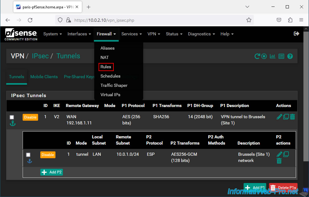
Next, go to the "IPsec" tab and click Add.
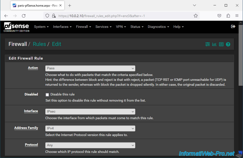
Configure the settings for this firewall rule like this:
- Action: Pass. To allow network traffic.
- Interface: IPsec. Since the network traffic comes from the IPsec tunnel connecting your 2 physical sites.
- Address Family: IPv4. In our case we only use IPv4.
- Protocol: Any. For convenience, we authorize all protocols (TCP, UDP, ICMP, ...). But you can choose to only allow certain protocols in your case for security reasons if you want.
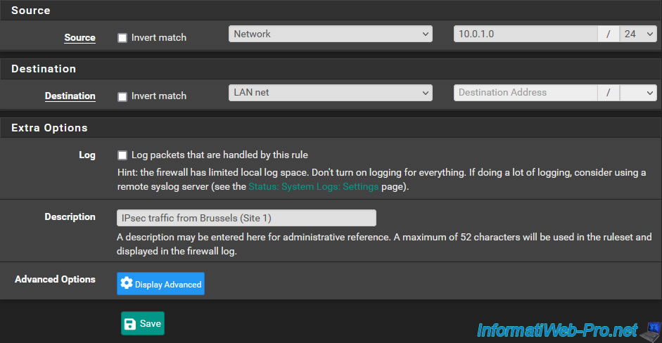
Next, configure these settings:
- Source: select "Network" and indicate the network used on site 1 (Brussels).
- Destination: select "LAN net". Which corresponds to the network you are on. In other words, site 2 (Paris) in our case.
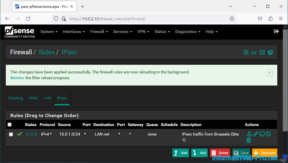
- Description: IPsec traffic from Brussels (Site 1).
Click: Apply Changes.
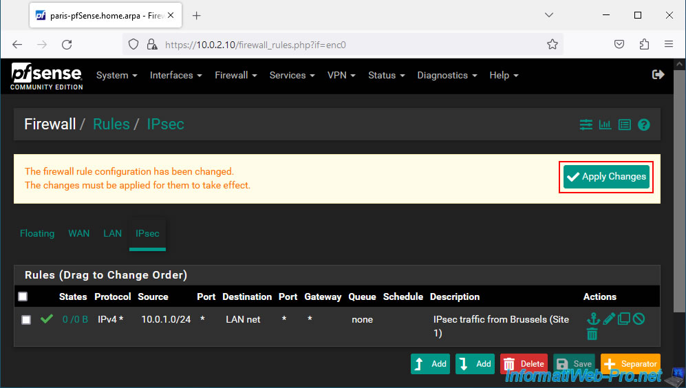
Inbound IPsec traffic is allowed to your LAN network.
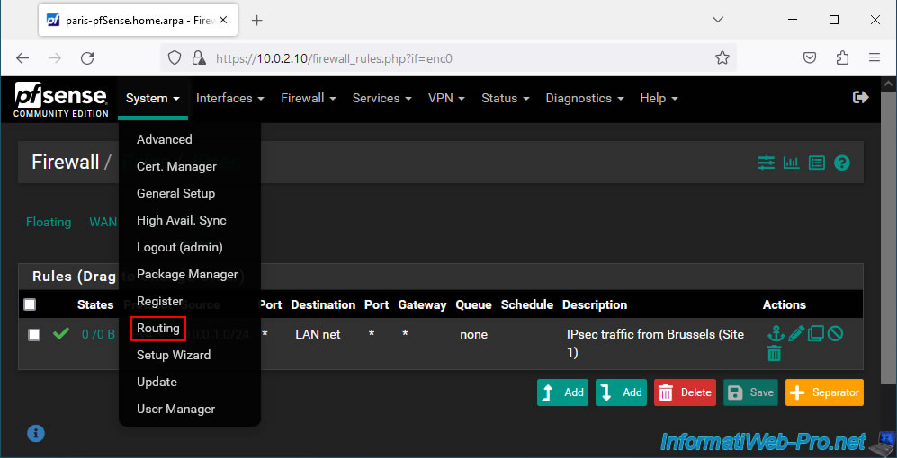
2.5. Define the LAN gateway used on site 2 (Paris)
If pfSense is not the default gateway for a client, a network packet may get lost or unnecessarily pass through the default gateway instead of directly through the IPsec tunnel.
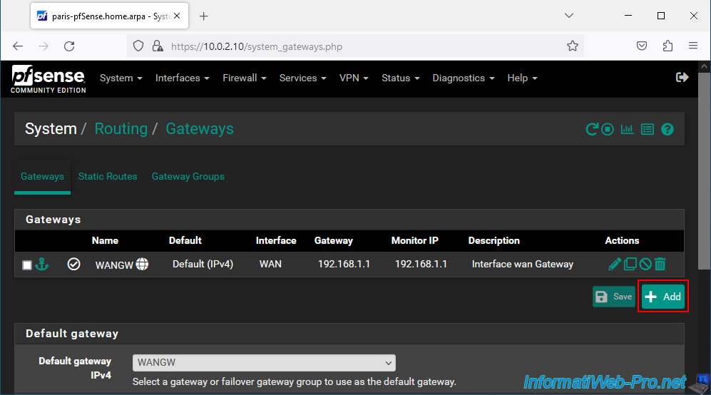
To resolve this problem, go to: System -> Routing.
On the "System / Routing / Gateways" page that appears, click on: Add.
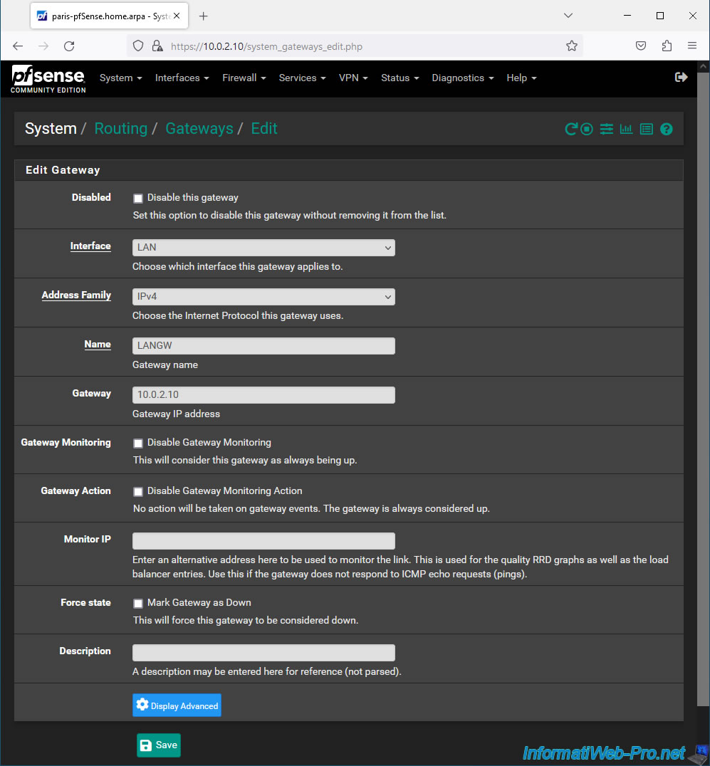
On the "Edit Gateway" page that appears, fill in these fields:
- Interface: LAN.
- Address Family: IPv4.
- Name: LANGW.
- Gateway: 10.0.2.10. Which corresponds to the IP address of the LAN interface of the pfSense machine where you are located
Then, click Save.
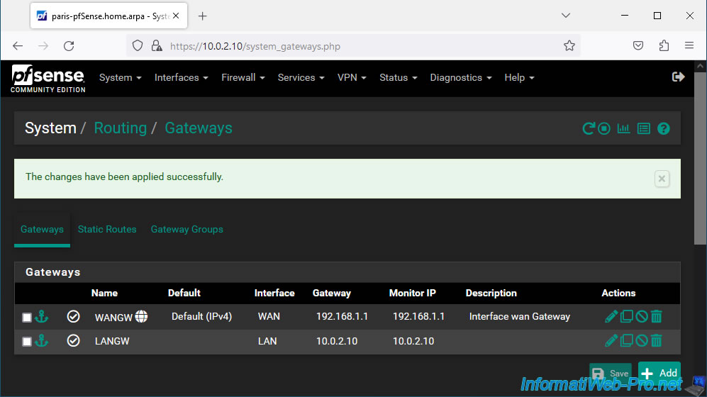
Click: Apply Changes.
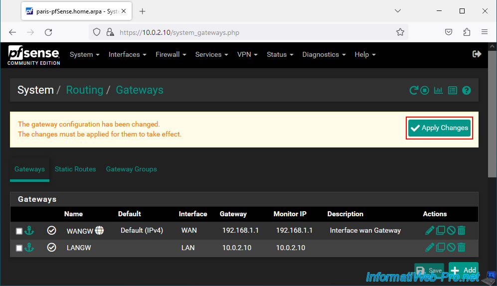
The LAN gateway has been set.
Share this tutorial
To see also
-
Firewall 6/4/2025
pfSense 2.6 - DNS resolution
-
Firewall 5/9/2025
pfSense 2.6 - Download and installation on VMware Workstation
-
Firewall 5/15/2025
pfSense 2.6 - Installation on VMware ESXi
-

Firewall 7/23/2025
pfSense 2.6 - Synchronize the clock from a time server (NTP)
No comment