- Firewall
- pfSense
- 08 August 2025 at 08:07 UTC
-

- 1/3

On pfSense, you can use the LACP protocol to benefit from fault tolerance on a network interface and/or increase the available network bandwidth.
Originally, the LACP (802.3ad) protocol is used on Cisco switches. But it is also available on switches from other brands, including those from Netgate (which run pfSense).
Important : using 2 network links using LACP does not mean that the throughput will be doubled. The bandwidth will be greater (almost double), but a network stream will not be able to exceed the bandwidth of a physical network link.
In other words, with 2 physical Gigabit Ethernet links, it is possible for 2 PCs to use almost 1 Gbs/s on the same LAG (LACP) at the same time. But a single PC will not be able to exceed a speed of 1Gbs/s even if it is the only one using the network at that time.
Source: LAGG (Link Aggregation) - LAGG Throughput | pfSense Documentation.
- Current pfSense network interfaces
- Delete the current LAN interface
- Add a LAGG interface (LACP)
- Assign the LAGG interface to a logical interface
- Enable the DHCP server on your new LAGG LAN interface
- Enable DNS resolver
- Allow network traffic on the LAGG LAN network interface
- Set a static IP address on your PC to access the physical switch
- Configure a LAG (LACP) on a Netgear GS810EMX (Nighthawk SX10) switch
- Working LAGG/LACP interface
- LACP link test (LAGG)
1. Current pfSense network interfaces
To begin, we installed pfSense with the WAN and LAN interfaces configured during its installation.
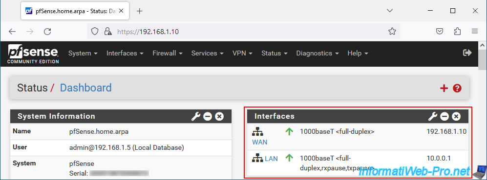
As you can see, in our case, we have 3 physical network cards:
- ue0: this is a USB network adapter or more precisely a network adapter connected via USB.
- ix0 and 1ix1: these are the 2 10 Gbit network ports on our Asus motherboard.
Warning : if you wish to test the configuration of a LAG (LACP protocol), do not use network adapters connected via USB for the network links which will be part of the LAG.
Chances are it won't work, even if pfSense recognizes them individually.
In our first test for our lab, we used 2 USB 3.0-Ethernet Gigabit TU3-ETG adapters from Trendnet (also recognized under the name "ASIX AX88179" under Linux). But the LAG (LACP) link was not working.
Once we reinstalled and reconfigured everything the same way, this time using the 10 Gbit Ethernet network ports on our motherboard for the LACP link, it worked the first time.
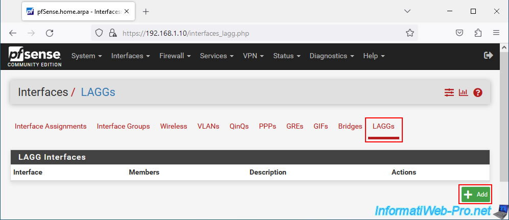
The configuration of LAGs will be carried out in the "LAGs" tab.

However, you will not be able to convert the current LAN interface into a LAG.
Indeed, as you can see, the "ix0" interface currently used by our "LAN" logical interface does not appear in the "Parent Interfaces" list for the configuration of a LAGG.
2. Delete the current LAN interface
As you saw earlier, we can't create a LAGG at the moment, because our physical network interface "ix0" is already used by our logical LAN interface.
To resolve the problem, you must:
- enable access to the pfSense web interface from its WAN interface by following this: pfSense 2.6 - Access to the web interface via the WAN interface.
- delete the current LAN logical interface as explained in the rest of this tutorial.
Important : before configuring the LACP link on pfSense and on your physical switch, you must disconnect the network cables on both sides for the desired physical network ports.
Once the network cables are unplugged, you will see a red icon appear for your LAN interface.
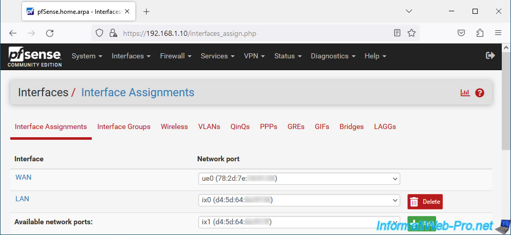
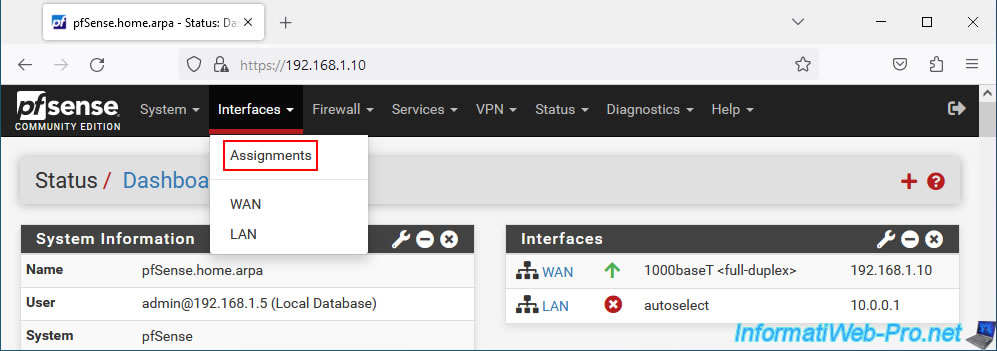
Now, go to: Interfaces -> Assignments.
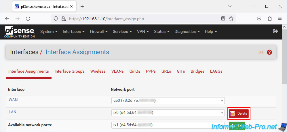
Click the "Delete" button (to the right of the LAN interface).
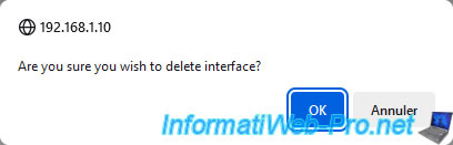
Confirm the deletion of this logical interface.
Plain Text
Are you sure you wish to delete interface?
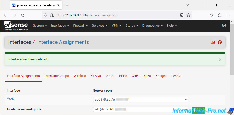
The "LAN" logical interface has been removed.
Plain Text
Interface has been deleted.
3. Add a LAGG interface (LACP)
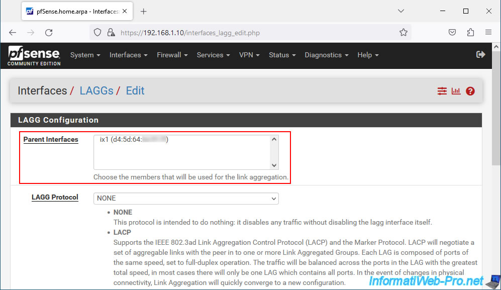
In the "LAGGs" tab, click on: Add.
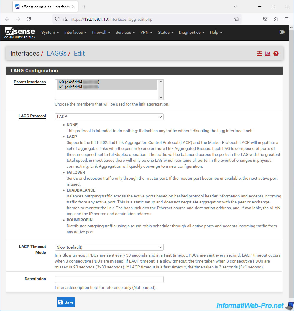
In the "Parent Interfaces" list, select the physical network interfaces that should be part of your LAGG.
In our case, we select the "ix0" and "ix1" interfaces which correspond to the 2 10 Gigabit Ethernet network ports on our Asus motherboard.
For LAGG Protocol, select "LACP" since it is LACP (IEEE 802.3ad) that we want to use.
When you select "LAGG Protocol: LACP", an option "LACP Timeout Mode" appears.
This allows you to configure the frequency at which LACP PDUs are sent:
- Slow (default) : les PDUs sont envoyés toutes les 30 secondes et le timeout se produira après 90 secondes.
En effet, le timeout se produit après 3 essais infructueux. - Fast : les PDUs sont envoyés toutes les secondes et le timeout se produira donc après seulement 3 secondes.
En effet, le timeout se produit à nouveau après 3 essais infructueux.
Source : LAGG (Link Aggregation) | pfSense Documentation.
Then, click Save.
Important : as a reminder, it is not possible to create a LAGG with USB network cards (USB network adapters).
Although pfSense recognizes them separately and no errors will appear here, you will see that the LACP link will never be "Up" on your physical switch.
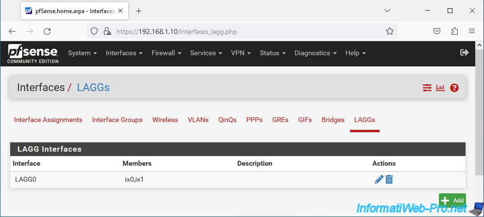
Your LAGG interface appears by default under the name "LAGG0".
4. Assign the LAGG interface to a logical interface
To be able to use the LAGG interface you have just created, you must assign it to a logical interface.
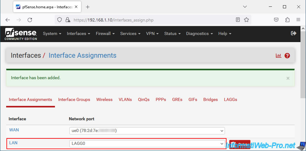
To do this, in the "Interface Assignments" tab, select the available network port (Available networks ports) "LAGG0" and click on: Add.
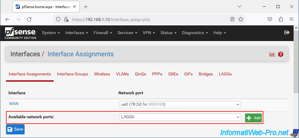
In our case, this interface "LAGG0" is assigned as logical interface "LAN".
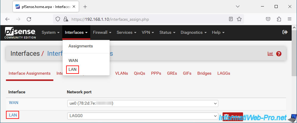
Click on its name to activate and configure it.
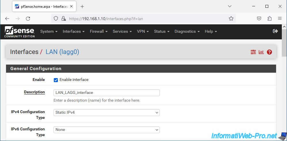
On the page that appears:
- Enable: check the "Enable interface" box to activate this logical interface.
- Description: indicate for example "LAN_LAGG_interface" to rename it.
- IPv4 Configuration Type: static IPv4. Allows you to define an IPv4 address.
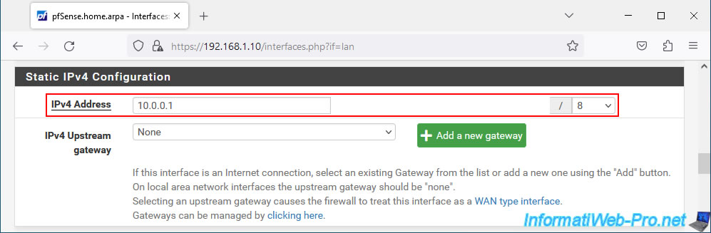
In the "Static IPv4 Configuration" section that appears, indicate an IPv4 address for this "LAN LAGG" network interface and select the associated subnet.
Typically "/8" for the "10.x.x.x" subnet or "/24" for the "192.168.1.x" subnet.
At the bottom of the page, click Save.
At the top of the page, click: Apply Changes.
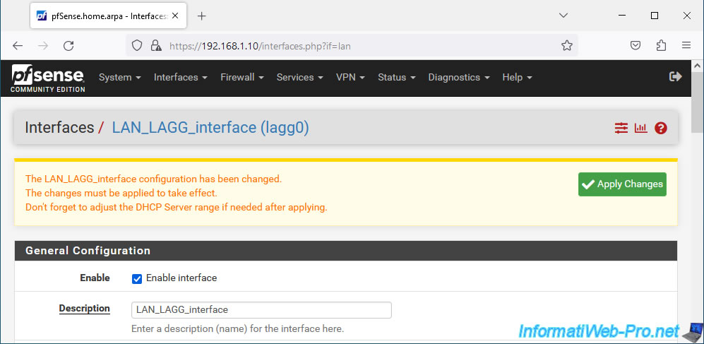
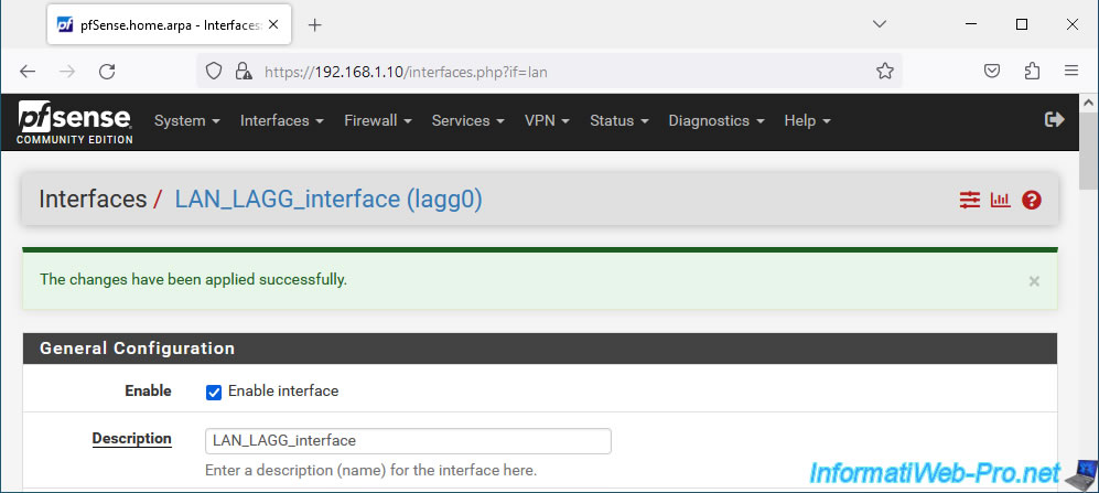
Modifications have been saved.
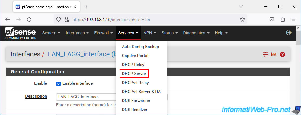
5. Enable the DHCP server on your new LAGG LAN interface
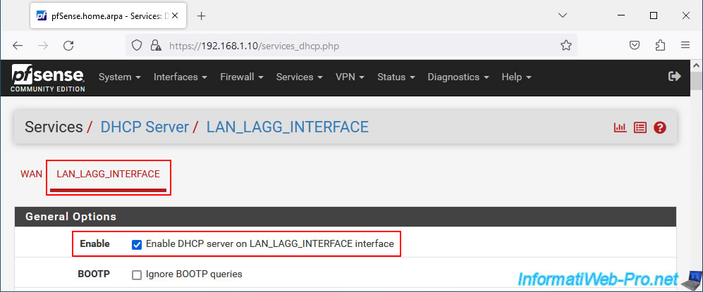
Now that the LAGG LAN interface is enabled and configured, go to: Services -> DHCP Server.
Go to the "LAN_LAGG_interface" tab and check the "Enable DHCP server on LAN_LAGG_interface" box to enable the DHCP server on your new network interface.
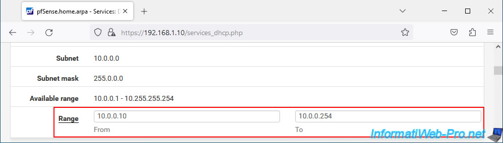
Specify a range of IP addresses to distribute on this LAGG LAN network.
In our case: 10.0.0.10 to 10.0.0.254.
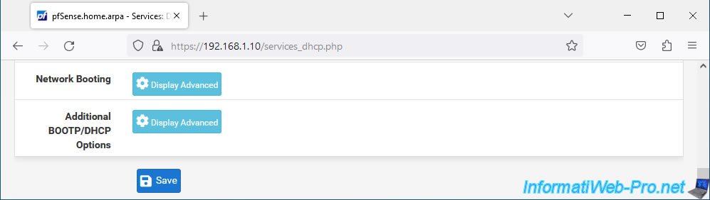
At the bottom of the page, click Save.
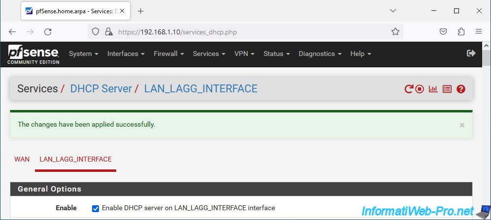
Your DHCP server has been activated and configured.
Share this tutorial
To see also
-
Firewall 7/30/2025
pfSense 2.6 - Backup and restore configuration
-
Firewall 9/12/2025
pfSense 2.6 - Create a site-to-site (S2S) VPN tunnel via OpenVPN secured with shared key (PSK)
-
Firewall 8/16/2025
pfSense 2.6 - Monitoring via SNMP and Zabbix 6
-
Firewall 5/23/2025
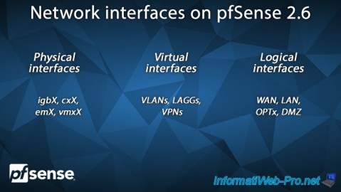
pfSense 2.6 - Network interfaces
You must be logged in to post a comment