Create a site-to-site (S2S) VPN tunnel via PPTP/L2TP on Windows Server 2022, 2016 and 2012

10.9. Connectivity tests between servers at 2 different physical sites (optional)
Optional: To prove that connectivity and routing are working properly, we added a web server at each physical site.
This proves that packet routing is being performed correctly by the two VPN servers, which also act as routers.
However, these web servers are not useful in a business environment. This is just an additional test to prove the functionality of this tutorial.
10.9.1. Install the web servers on the 2 physical sites
On site 1 (Brussels), we added a "brux-web" server with the IP address "10.0.1.11" (to stay in the same "10.0.1.X" network as this site 1 (Brussels)).

We installed the "Web Server (IIS)" role on this "brux-web" server.

On site 2 (Paris), we added a "paris-web" server with the IP address "10.0.2.11".
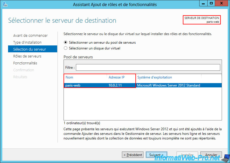
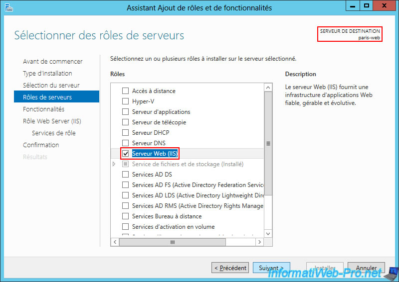
Again, we installed the "Web Server (IIS)" role on this server.
10.9.2. Testing access to the 2 web servers (from the 2 physical sites)
From the web server "brux-web" we tried to access our own web server (10.0.1.11) and we can see the "IIS 8" page appear.

In a second tab of the same web browser, we try to access the remote web server "paris-web" (10.0.2.11) and, as expected, it works.
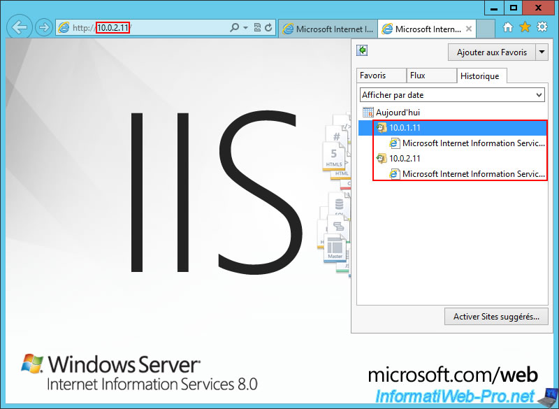
Note that the reverse test also works. From the "paris-web" web server, we also have access to the "brux-web" web server (10.0.1.11) and the local "paris-web" web server (10.0.2.11).

As you can see from the Internet Explorer history, we were able to access both web servers (10.0.1.11 and 10.0.22.11) from the same server.
10.9.3. Allow ping on your web servers
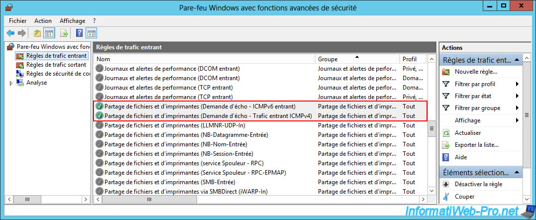
If you want to test the connectivity between these 2 servers again via the "ping" command, don't forget to enable the rules below for the incoming traffic of these 2 servers:
- File and Printer Sharing (Echo Request - ICMPv4-In).
- File and Printer Sharing (Echo Request - ICMPv6-In).
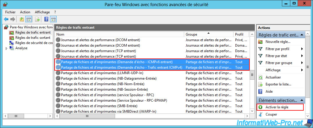
Now, ping is allowed.
10.9.4. Connectivity tests between the 2 web servers of different physical sites (via ping)
Again, to ensure that both routing and VPN tunnels are configured correctly, it's best to test the ping between your two web servers (in both directions).
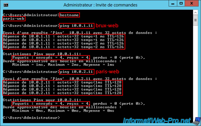
To begin with, you can see that our web server "brux-web" can communicate without any problems with itself (brux-web / 10.0.1.11) and with the remote web server (paris-web / 10.0.2.11).
Batch
ping 10.0.1.11
Plain Text
Reply from 10.0.1.11: bytes=32 time<1ms TTL=128
...

    Packets : Sent = 4, Received = 4, ...
Batch
ping 10.0.2.11
Plain Text
Reply from 10.0.2.11: bytes=32 time=1 ms TTL=126
...

    Packets : Sent = 4, Received = 4, ...

Then, you can see that our web server "paris-web" can communicate without any problem with the remote web server (brux-web / 10.0.1.11) and with itself (paris-web / 10.0.2.11).
11. Routing information about your VPN servers
A short network tutorial with the routing information you can view from the command line on your two VPN servers.
Note: there is nothing to modify or configure.
This is for informational purposes only to help you understand what's happening in the network and how network packets reach the correct destination thanks to your two VPN servers, which also act as routers.
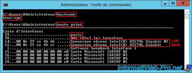
On the "brux-vpn" VPN server at Site 1 (Brussels), open a command prompt and simply type the command "route print."
Batch
route print
In the list of interfaces on this VPN server "brux-vpn" of site 1 (Brussels), you will find in particular:
- Paris: the dial-on-demand interface allows you to access the remote network (site 2 (Paris)) from the local site network (site 1 (Brussels)).
- Intel(R) 82574L Gigabit Network Connection #2: the LAN network adapter connected to the LAN (10.0.1.X).
- Intel(R) 82574L Gigabit Network Connection: the WAN network adapter connected to the LAN (192.168.1.X).
Plain Text
Interface List
29...........................paris
...
14...00 0c 29 се 4b d6 ......Intel(R) 82574L Gigabit Network Connection #2
12...00 0с 29 се 4b cc ......Intel(R) 82574L Gigabit Network Connection
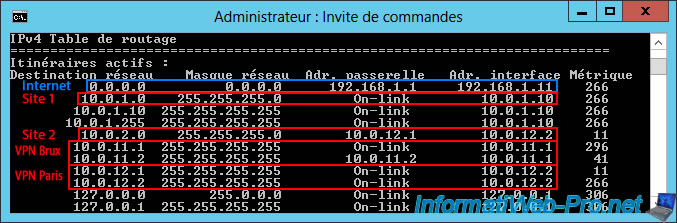
A little further down, you'll find the routing table for the "IPv4" protocol.
As you can see:
- 0.0.0.0: means all network traffic not affected by the remaining routes displayed in the routing table (including network traffic destined for the Internet) will be sent to the gateway "192.168.1.1" (which corresponds to the default gateway specified in the configuration of the "WAN" network card connected to the Internet).
- 10.0.1.0: network traffic destined for the "10.0.1.0" network (i.e., the network at Site 1 (Brussels)) is handled by the "On-link" gateway (which simply means that it is the local network at this site) and that the IP address of the interface (network card) is "10.0.1.10" (= the IP address of the "LAN" network card of this "brux-vpn" server).
- 10.0.2.0: network traffic destined for the "10.0.2.0" network (i.e., the remote network located at Site 2 (Paris)) is handled by the "10.0.12.1" gateway (which is an IP address within the IP address range intended for clients of the remote VPN server "paris-vpn").
Therefore, network traffic destined for the "10.0.2.0" network will be sent to the remote site via the "paris" demand-dial connection, which has received an IP address of "10.0.12.X" from the remote VPN server "paris-vpn" (Site 2 (Paris)). - 10.0.11.X: this concerns internal network traffic within the VPN tunnel for clients of the "brux-vpn" VPN server at Site 1 (Brussels).
- 10.0.12.X: this concerns internal network traffic within the VPN tunnel for clients of the "paris-vpn" VPN server at Site 2 (Paris).
You can also see that two IP addresses are used per site, even though there is only one on-demand connection. Indeed, there is a local IP address (assigned to the local interface) and a remote IP address (assigned by the remote VPN server) to enable a bidirectional connection.
Plain Text
IPv4 Route Table
===========================================================================
Active Routes:
Network Destination        Netmask          Gateway        Interface  Metric
          0.0.0.0          0.0.0.0      192.168.1.1     192.168.1.11     266
         10.0.1.0    255.255.255.0         On-link         10.0.1.10     266
...
         10.0.2.0    255.255.255.0        10.0.12.1        10.0.12.2      11
        10.0.11.1  255.255.255.255         On-link         10.0.11.1     296
        10.0.11.2  255.255.255.255        10.0.11.2        10.0.11.1      41
        10.0.12.1  255.255.255.255         On-link         10.0.12.2      11
        10.0.12.2  255.255.255.255         On-link         10.0.12.2     266
A little further down, just after the IPv4 routing table, you'll find the list of persistent routes.
In this case, you'll see that all network traffic (0.0.0.0) is supposed to be sent to the IP address "192.168.1.1" (which corresponds to the default gateway specified in the TCP/IP configuration of the "WAN" interface of this VPN server).
However, the truth about network routing is above (in the routing table).
Plain Text
Persistent Routes:
  Network Address          Netmask  Gateway Address  Metric
          0.0.0.0          0.0.0.0      192.168.1.1       1

Similarly, go to the remote VPN server "paris-vpn", open a command prompt and type the command "route print" again.
Batch
route print
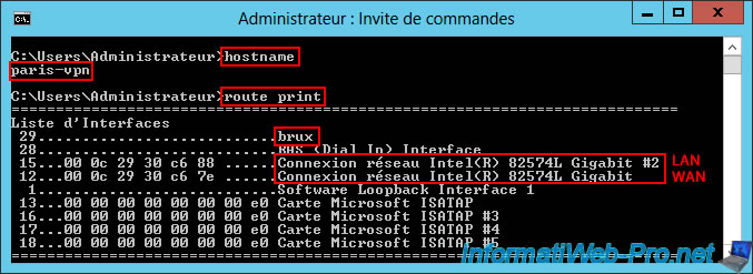
In the list of interfaces on this VPN server "paris-vpn" of site 2 (Paris), you will find in particular:
- brux: the dial-on-demand interface allowing you to access the remote network (site 1 (Brussels)) from the local site network (site 2 (Paris)).
- Intel(R) 82574L Gigabit Network Connection #2: the LAN network adapter connected to the LAN (10.0.2.X).
- Intel(R) 82574L Gigabit Network Connection: the WAN network adapter connected to the LAN (192.168.1.X).
Plain Text
Interface List
29...........................brux
...
15...00 0c 29 30 c6 88 ......Intel(R) 82574L Gigabit Network Connection #2
12...00 0с 29 30 c6 7e ......Intel(R) 82574L Gigabit Network Connection
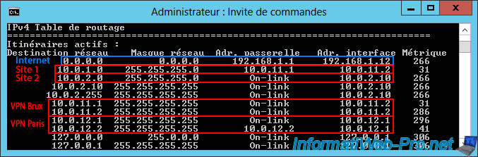
A little further down, you'll find the routing table for the "IPv4" protocol.
As you can see:
- 0.0.0.0: again, this means that all network traffic not affected by the remaining routes displayed in the routing table (including Internet traffic) will be sent to the gateway "192.168.1.1" (i.e., via the "WAN" network adapter).
- 10.0.1.0: network traffic destined for the network "10.0.1.0" (i.e., the remote network located at Site 1 (Brussels)) is handled by the gateway "10.0.11.1" (which is an IP address within the IP address range intended for clients of the remote VPN server "brux-vpn").
Therefore, network traffic destined for the "10.0.1.0" network will be sent to the remote site via the "brux" on-demand connection, which has received an IP address of "10.0.11.X" from the remote VPN server "brux-vpn" (site 1 (Brussels)). - 10.0.2.0: network traffic destined for the "10.0.2.0" network (i.e., the network of site 2 (Paris)) is managed by the "On-link" gateway (which simply means that it is the local network at this site) and the interface (network card) IP address is "10.0.2.10" (= the IP address of the "LAN" network card of this "paris-vpn" server).
- 10.0.11.X: again affects internal network traffic within the VPN tunnel for clients of the "brux-vpn" VPN server at Site 1 (Brussels).
- 10.0.12.X: again affects internal network traffic within the VPN tunnel for clients of the "paris-vpn" VPN server at Site 2 (Paris).
Again, there are two IP addresses per VPN tunnel (one local IP address and one remote IP address).
Plain Text
IPv4 Route Table
===========================================================================
Active Routes:
Network Destination        Netmask          Gateway        Interface  Metric
          0.0.0.0          0.0.0.0      192.168.1.1     192.168.1.12     266
         10.0.1.0    255.255.255.0        10.0.11.1        10.0.11.2      31
         10.0.2.0    255.255.255.0         On-link         10.0.2.10     266
...
        10.0.11.1  255.255.255.255         On-link         10.0.11.2      31
        10.0.11.2  255.255.255.255         On-link         10.0.11.2     286
        10.0.12.1  255.255.255.255         On-link         10.0.12.1     296
        10.0.12.2  255.255.255.255        10.0.12.2        10.0.12.1      41
Just below the IPv4 routing table, you'll find the list of persistent routes again.
Again, you'll see that all network traffic (0.0.0.0) is supposed to be sent to the IP address "192.168.1.1" (including via the "WAN" interface of this VPN server).
However, the actual network routing performed is above (in the routing table).
Plain Text
Persistent Routes:
  Network Address          Netmask  Gateway Address  Metric
          0.0.0.0          0.0.0.0      192.168.1.1       1

Share this tutorial
To see also
-

Windows Server 4/28/2012
WS 2003 - NAT and network routing
-
Windows Server 8/8/2012
WS 2008 - NAT and network routing
-

Windows Server 4/22/2015
WS 2012 - NAT and network routing
-

Windows Server 12/3/2016
WS 2012 - Routing and VPN server
No comment