- VMware
- 17 August 2022 at 14:01 UTC
-


If you've never touched the network configuration of a VMware ESXi hypervisor before, you've come to the right place.
Indeed, in this tutorial, you will learn the basics of network management on VMware ESXi and you will thus know how virtual machines can access the physical network via, in particular, virtual switches created on your VMware ESXi hypervisor.
1. Port groups
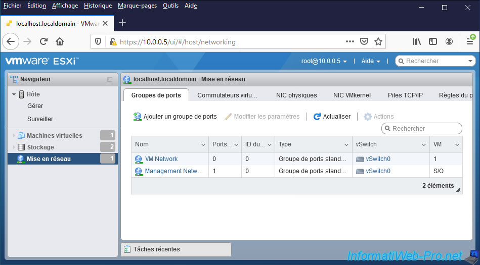
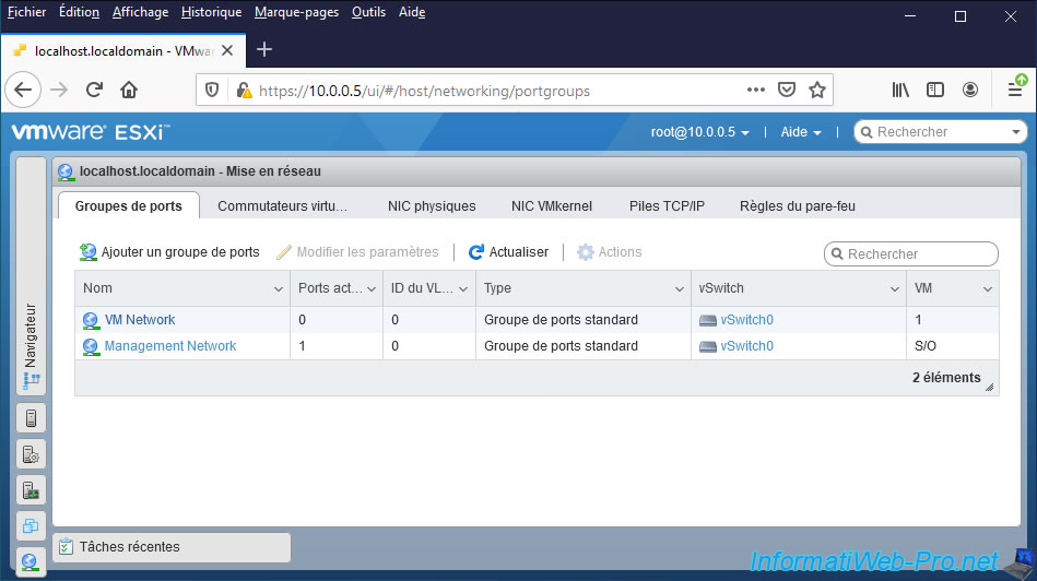
If you look in "Networking -> Port groups" of VMware ESXi, you will see that there are 2 port groups by default :
- VM Network : port group on which you can connect your virtual machines
- Management Network : port group used for managing your VMware ESXi hypervisor
Note that you can create up to 512 port groups per vSwitch. Which is more than enough.
Additionally, you can force a portgroup to use a specific VLAN ID to isolate network traffic from 2 portgroups that would be on the same vSwitch.
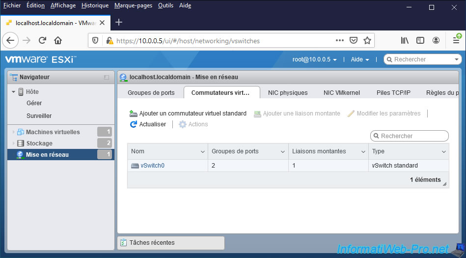
In the "Virtual switches" tab, you will find a "vSwitch Standard" type virtual switch named "vSwitch0".
This virtual switch acts as an intermediary between the physical network adapters (NICs) and the port groups.
Note that it's not possible to directly connect your virtual machines on a virtual switch created on VMware ESXi, but only on a port groups.
Hence the presence of a "VM Network" port group created by default when installing your VMware ESXi hypervisor.
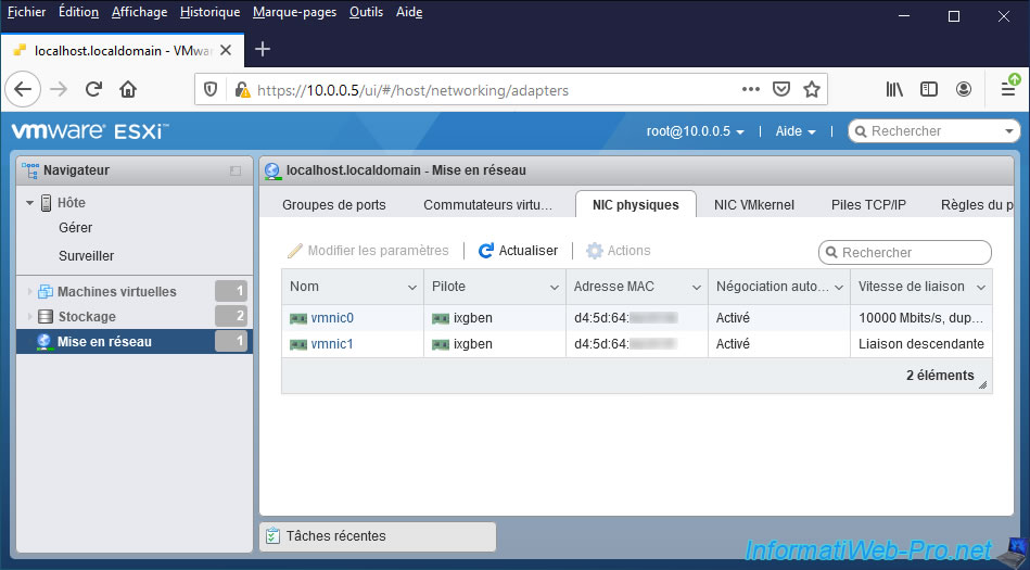
Finally, in the "Physical NICs" tab, you will find the list of physical network adapters present in your computer or server.
Note that if you have physical network adapters with multiple network ports, each network port will appear in this list.
In our case, we have an "ASUS WS X299 SAGE/10G" motherboard with 2 "10 Gb/s" Ethernet ports.
VMware ESXi therefore displays 2 "physical network adapters" since each physical network port has a different MAC address.
If you are a little observant, you will see that there is only one network cable plugged into the "vmnic0" network card. Since the link speed is only displayed for this one and not for the "vmnic1" network adapter.
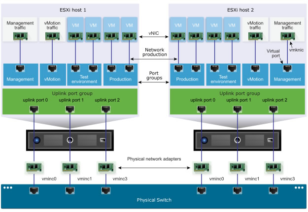
To make these notions of port groups, virtual switches and physical network adapters a little clearer, here is a diagram present in the official VMware documentation.
In the diagram below, you can see that :
- there is an architecture with 2 physical ESXi servers
- the virtual network adapters of 2 virtual machines on each ESXi server are connected to the "Production" and "Test environment" port groups
- these port groups (in dark blue) are "connected" to an "Uplink port group"
- in the diagram below, the green block named "Uplink port group" actually corresponds to a virtual switch (or in other words, a vSwitch)
- the virtual switch allows you to create a set of physical network ports (called "uplink port" in the diagram below)
- these physical network ports are those of the physical network adapters (vmnic0, vmnic1 and vmnic3) of the server
- these physical network ports are connected to your company's physical switch or router with physical network cables
Important : if you have multiple VMware ESXi hypervisors, make a habit of naming your port groups with the same names.
Indeed, when you move a virtual machine hot (thanks to VMware vMotion technology) from one VMware ESXi hypervisor to another, this will allow the virtual machine to reconnect correctly to the network on the destination VMware ESXi hypervisor. Since vMotion will find a port group with the same name as on the source VMware ESXi hypervisor.
In short, to summarize, here is the standard network path from the physical switch to the virtual machine : physical switch -> physical network adapter of the server -> virtual switch (created on the ESXi server) -> port group (created on the ESXi server) -> virtual network adapter of the virtual machine.
2. Virtual switch (vSwitch)
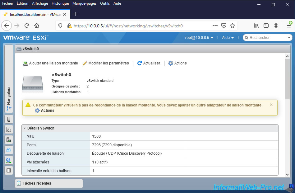
As you can see, the "vSwitch0" virtual switch created by default by VMware ESXi is of type "vSwitch Standard".
This corresponds to a simple virtual switch and it can be created only on the VMware ESXi hypervisor.
In the case of VMware ESXi, you have no choice since you will only have access to the vSphere Standard Switch (VSS).
However, if you switch one day to the paid version of this product, namely the "VMware vSphere" solution, you can also create vSphere Distributed Switch (VDS).
As you can see, VMware ESXi tells you by default that this virtual switch has no uplink (= network adapter) redundancy.
To solve the problem, it suffices to add an additional network adapter to this virtual switch (vSwitch) to obtain fault tolerance.
If one of the NICs fails, network traffic can continue to pass through the other physical NIC (uplink).

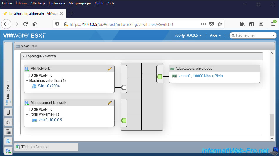
If you look at the bottom of this "vSwitch0" page, you will find a "vSwitch topology" section.
Thanks to this network topology, you can see that the 2 port groups "VM Network" and "Management Network" are connected on this virtual switch "vSwitch0".
And that this virtual switch "vSwitch0" uses a single physical network adapter named "vmnic0" by VMware.
3. Settings inheritance
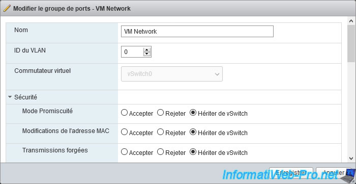
When you create a port group (or edit an existing one), you will see that some of the settings are the same as for the switches.
In fact, the value of these common settings are inherited by default from the virtual switch (vSwitch) on which the port group concerned is located.
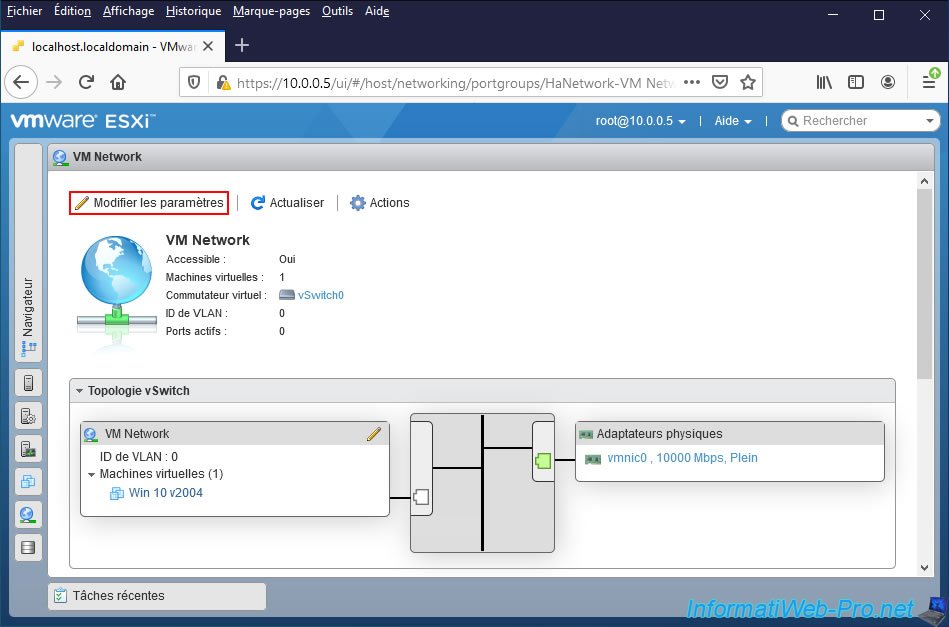
To see it, click for example on "VM Network".
Then, click on : Edit settings.
Note that you can easily see some information thanks to the "vSwitch topology" diagram :
- the VLAN ID used on this port group or 0 if you don't use this option
- the list of virtual machines connected to this ports group (whether they are started or not)
- the list of physical network adapters through which network traffic for this port group can pass.
However, as a reminder, the selection of physical network adapters is carried out at the level of the virtual switch (vSwitch) and not in the settings of the ports group.
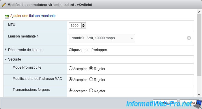
As you can see there are different settings offered, but their values are usually inherited from vSwitch.
If you try to edit the vSwitch concerned by this ports group, you will find these common settings, as well as their real values.
4. Associate network adapters (NIC Teaming)
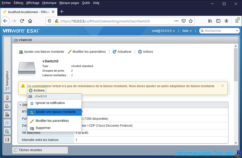
As noted earlier, by default, VMware ESXi tells you that your virtual switch doesn't have uplink redundancy when it uses only one physical NIC.
Add a physical network adapter in your server, then click on "Actions -> Add uplink" or directly on "Add uplink".
The new physical network adapter physically added to your server should appear in the "Uplink 2" list since it's not yet in use by a virtual switch.
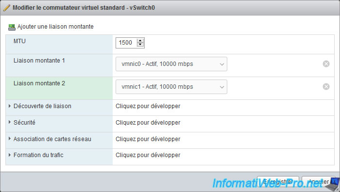
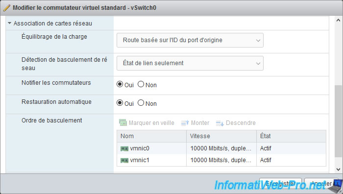
In the settings of this standard virtual switch (vSwitch0), you will find a "NIC teaming" section with different settings :
- Load balancing : allows you to choose how network traffic will be distributed across the different physical network adapters assigned to this virtual switch.
- Network failover detection : allows you to choose how the failure of a network link will be detected.
- Notify switches : allows you to notify or not the physical switch of the switchover.
If this option is enabled, when a virtual network adapter is connected to a distributed switch (vDS) or when its traffic will be handled by another physical network adapter, the physical switch will be notified of this change so that it can update its lookup table (ARP table).
This reduces latency during failover and during migrations via vMotion. - Failback : when a fault is repaired, this determines whether the physical adapter that was faulty should become active again automatically or not.
- Failover order : allows you to use an active/standby or active/active mode.
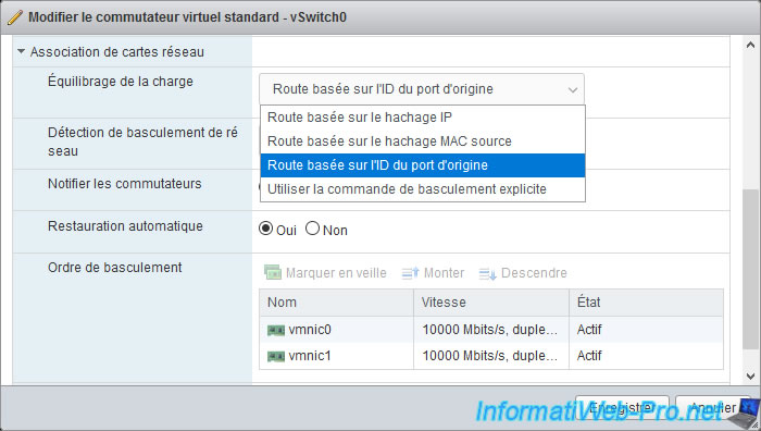
For the load balancing method, you have 4 options to choose from :
- Route based on IP hash : allows you to select a network path based on the source and destination IP addresses. This means that a virtual machine's traffic can pass through multiple network adapters (depending on the destination IP), but this requires the configuration of an EtherChannel on the physical switch.
However, this configuration is the most used in production. - Route based on source MAC hash : balances the load by ensuring that the vSwitch will always assign the same physical NIC to the same VM (since its MAC address will not have changed). Its network path will therefore not change.
- Route based on originating port ID (or "Route based on originating virtual port" on vCenter) : allows you to balance the load quite easily and be pretty sure it will work without any issues.
When the virtual machine sends its 1st network frame through the network, the vSwitch chooses a physical network adapter through which its traffic will pass and all future network frames of this VM will continue to pass through this physical network adapter.
However, if you shut down, restart, or migrate your virtual machine later, the choice of physical network adapter may have changed. - Use explicit failover command : disable load balancing and thus only benefit from fault tolerance based on the failover detection method selected just below.
For more information on the operation, advantages and disadvantages of each of these methods, refer to the "Load Balancing Algorithms Available for Virtual Switches" page of the official VMware documentation.
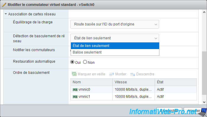
For the "Network failover detection" setting, which concerns the detection of network failures, you will have the choice between :
- Link status only : used to detect the failure of the physical network adapters of your VMware ESXi hypervisor, as well as the failure of the physical switches to which these physical network adapters are attached.
However, if a switch located further away (or in other words, a level 2 switch) fails, VMware ESXi will not detect it and network packets may be lost when they arrive at a failed switch in your network. - Beacon only (or "Beacon probing" on vCenter) : allows better detection of network failures thanks to network packets sent over the network at regular intervals to ensure that the physical network adapters, as well as the physical switches on your network are still functional.
While this method is more comprehensive, it only works with EtherChannel and requires at least 3 physical NICs to be used.
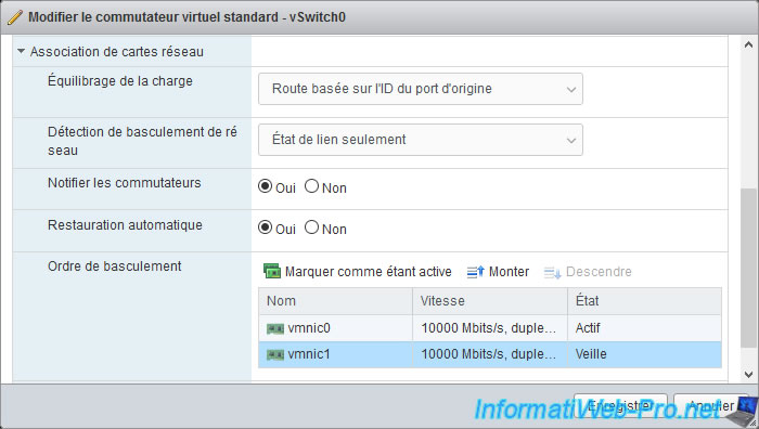
For the failover order, this allows you to choose the order in which the physical network adapters assigned to this virtual switch (vSwitch) should be used.
You can also mark specific physical network adapters "standby" or "active".
If you have enabled load balancing on this virtual switch, VMware ESXi will distribute the network load through the physical NICs in the "active" state.
Network adapters marked as "standby" will only be used to replace a network adapter in "active" state when a fault is detected on it. Whether it's a failure of the physical network adapter concerned or of its network link (failure of the network cable or of the physical switch to which it's connected).
To mark a network adapter to "standby" state, select the desired physical network adapter and click on : Mark standby.

As expected, the status of the selected physical network adapter becomes : Standby.
To put a physical network adapter back in "Active" state, select this standby network adapter and click on : Mark active.
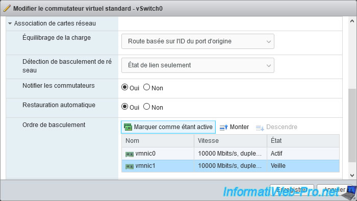
The selected network adapter is once again in the "Active" state.
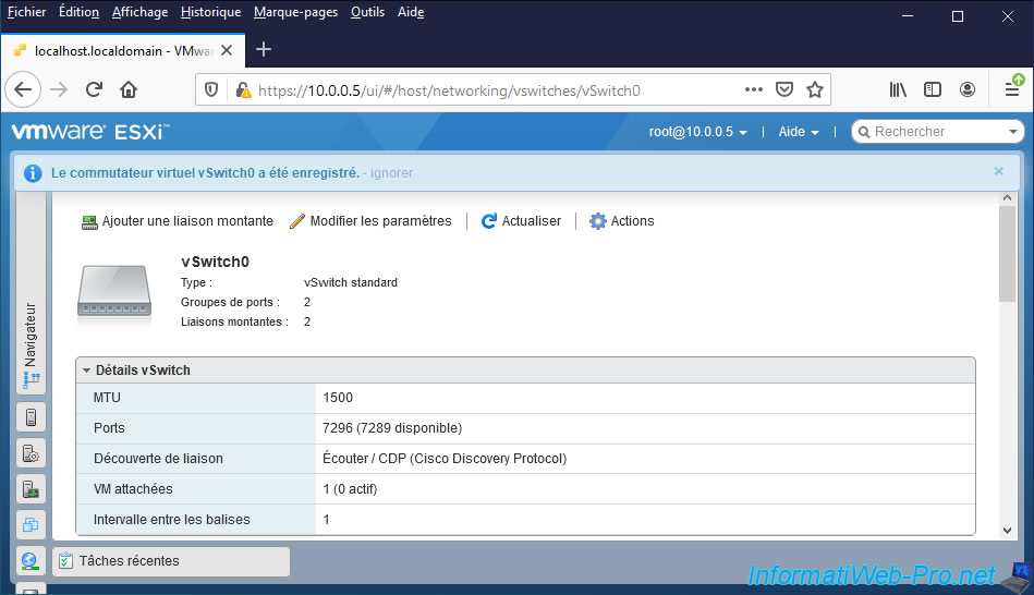
Finally, click on : Save.

The "Virtual switch vSwitch0 was successfully saved" message appears.
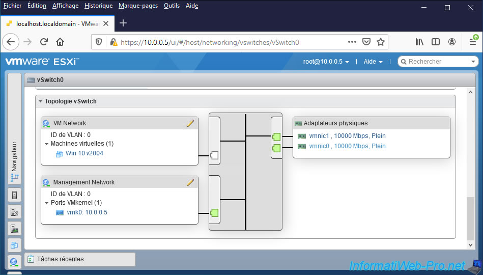
If you look at the topology of this virtual switch (vSwitch0) at the bottom of the page, you will see that it now uses 2 physical network adapters.
Share this tutorial
To see also
-
VMware 3/3/2023
VMware ESXi 6.7 - Add a VMkernel interface
-
VMware 2/24/2023
VMware ESXi 6.7 - Create a new virtual network
-
VMware 3/24/2023
VMware ESXi 6.7 - Enable Jumbo frame support
-
VMware 3/17/2023
VMware ESXi 6.7 - Limit outbound bandwidth
You must be logged in to post a comment